Brick sprinkling equipment for construction

A technology for sprinkler equipment and construction, applied in the field of brick sprinkler equipment for construction, can solve the problems of slow natural cooling rate of bricks, scald, etc., and achieve the effect of increasing the scope of water spraying and accelerating the cooling rate.

Active Publication Date: 2020-02-28
度测(上海)科技服务中心
View PDF10 Cites 0 Cited by
  • Summary
  • Abstract
  • Description
  • Claims
  • Application Information

AI Technical Summary

Problems solved by technology

[0003] To sum up, it is necessary to develop a construction brick sprinkler equipment that accelerates the cooling of bricks and sprinkles water comprehensively, so as to overcome the shortcomings of slow natural cooling of bricks and unintentional burns in the prior art.

Method used


Image

  • Brick sprinkling equipment for construction
  • Brick sprinkling equipment for construction
  • Brick sprinkling equipment for construction

Examples


Embodiment 1

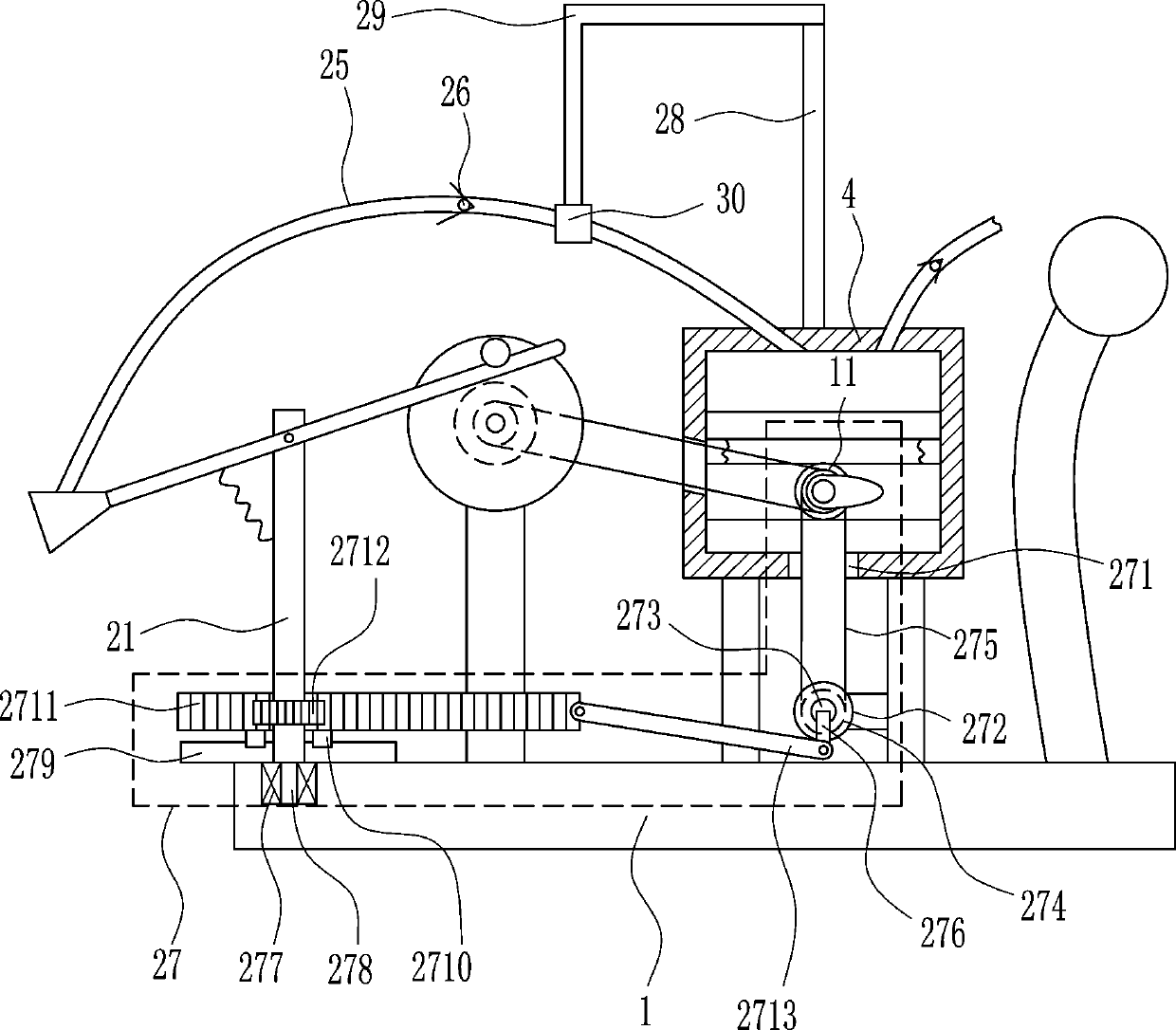
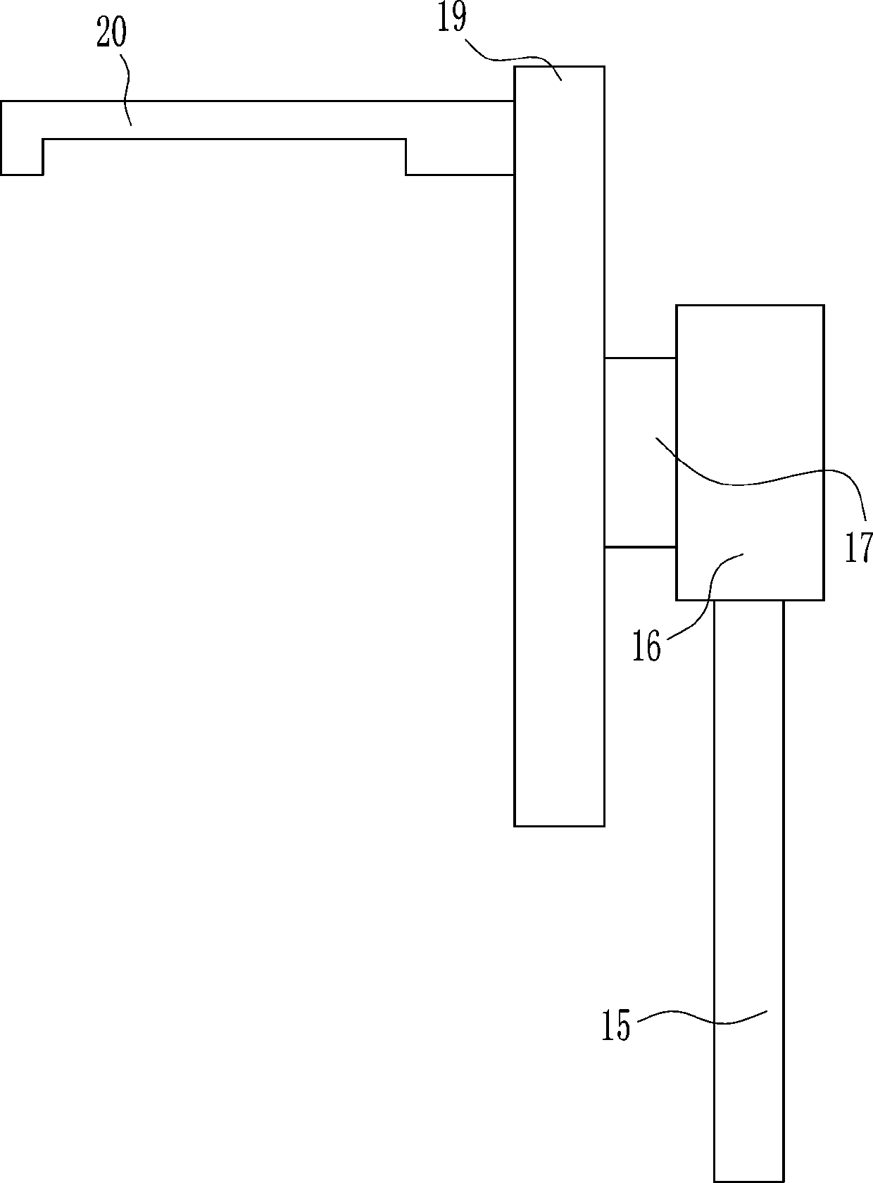
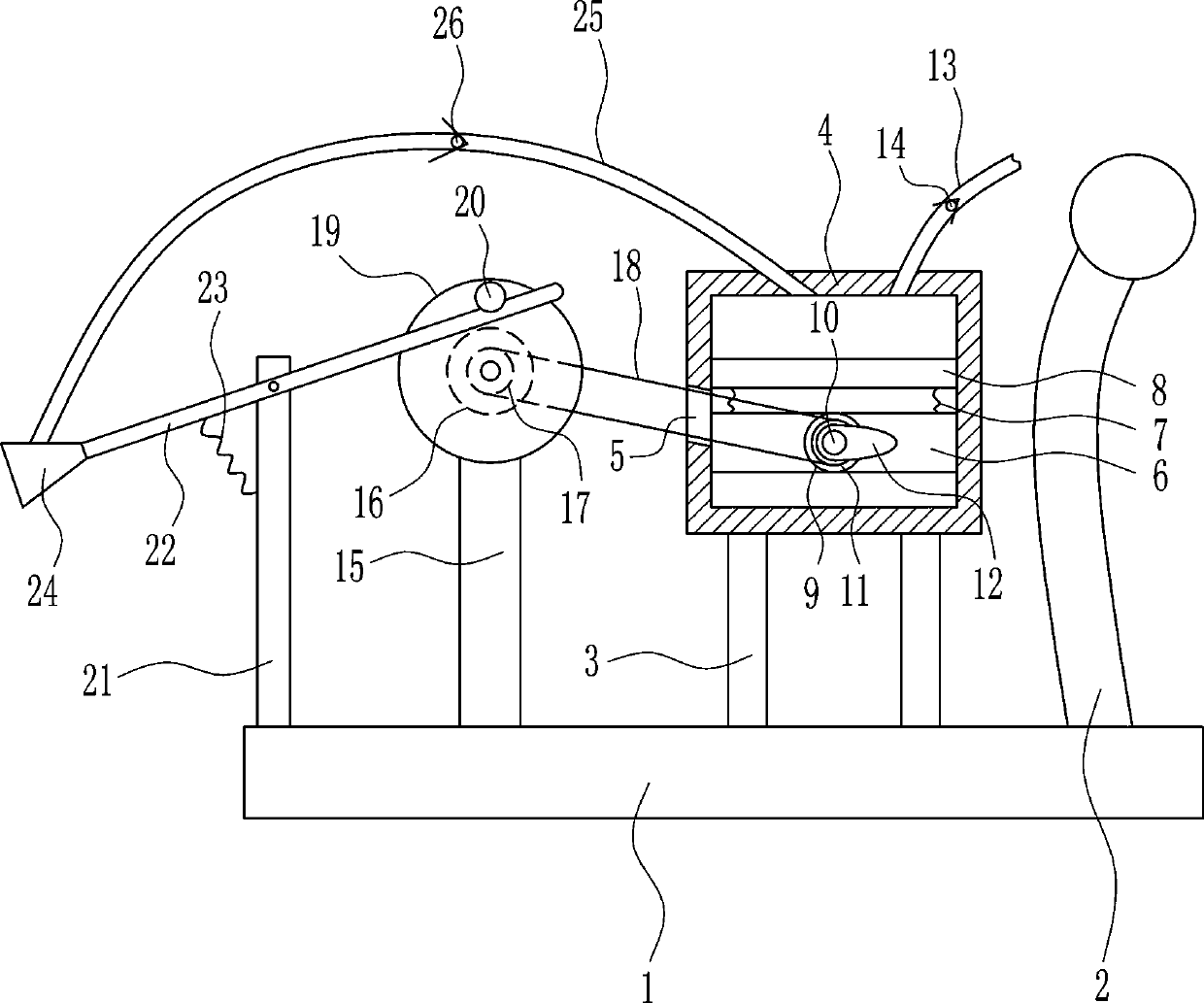
[0028] A brick sprinkling equipment for building, such as Figure 1-6As shown, it includes a bottom plate 1, a push handle 2, a first pole 3, a cylinder body 4, a first mounting plate 6, a first spring 7, a piston 8, a first bearing seat 9, a first rotating shaft 10, and a first pulley 11. , cam 12, first hose 13, first one-way valve 14, second pole 15, motor 16, second pulley 17, first flat belt 18, disc 19, concave rod 20, first connecting rod 21. Swing rod 22, second spring 23, nozzle 24, second hose 25 and second one-way valve 26, push handle 2 is provided on the top right side of base plate 1, and two first support rods are provided on the top right side of base plate 1 3. The first support rod 3 is on the left side of the pusher 2, the top of the first support rod 3 is connected to the cylinder body 4, and the middle part of the left wall of the cylinder body 4 has a first through hole 5, between the inner lower part of the left and right walls of the cylinder body 4 Th...

Embodiment 2

[0030] A brick sprinkling equipment for building, such as Figure 1-6 As shown, it includes a bottom plate 1, a push handle 2, a first pole 3, a cylinder body 4, a first mounting plate 6, a first spring 7, a piston 8, a first bearing seat 9, a first rotating shaft 10, and a first pulley 11. , cam 12, first hose 13, first one-way valve 14, second pole 15, motor 16, second pulley 17, first flat belt 18, disc 19, concave rod 20, first connecting rod 21. Swing rod 22, second spring 23, nozzle 24, second hose 25 and second one-way valve 26, push handle 2 is provided on the top right side of base plate 1, and two first support rods are provided on the top right side of base plate 1 3. The first support rod 3 is on the left side of the pusher 2, the top of the first support rod 3 is connected to the cylinder body 4, and the middle part of the left wall of the cylinder body 4 has a first through hole 5, between the inner lower part of the left and right walls of the cylinder body 4 T...

Embodiment 3

[0033] A brick sprinkling equipment for building, such as Figure 1-6 As shown, it includes a bottom plate 1, a push handle 2, a first pole 3, a cylinder body 4, a first mounting plate 6, a first spring 7, a piston 8, a first bearing seat 9, a first rotating shaft 10, and a first pulley 11. , cam 12, first hose 13, first one-way valve 14, second pole 15, motor 16, second pulley 17, first flat belt 18, disc 19, concave rod 20, first connecting rod 21. Swing rod 22, second spring 23, nozzle 24, second hose 25 and second one-way valve 26, push handle 2 is provided on the top right side of base plate 1, and two first support rods are provided on the top right side of base plate 1 3. The first support rod 3 is on the left side of the pusher 2, the top of the first support rod 3 is connected to the cylinder body 4, and the middle part of the left wall of the cylinder body 4 has a first through hole 5, between the inner lower part of the left and right walls of the cylinder body 4 T...


PUM


Abstract

The invention relates to watering equipment, in particular to brick watering equipment for a building. The brick watering equipment for the building can accelerate the cooling and watering of bricks comprehensively. The brick watering equipment for the building comprises a bottom plate, a pushing hand, a cylinder body and the like. The pushing hand is arranged on the right side of the top of the bottom plate. Two first support rods are arranged on the right side of the top of the bottom plate. The first support rods are arranged on the left side of the pushing hand. The top ends of the first support rods are connected with the cylinder body. A first through hole is formed in the middle of the left wall of the cylinder body. A first mounting plate is connected between the lower parts of theinner sides of the left wall and the right wall in the cylinder body. By the adoption of the brick watering equipment for the building, the effects of accelerating the cooling and watering of the bricks are achieved; a spray head swings up and down, so that the spray head can cool the bricks more comprehensively; a rotating device drives the spray head to swing back and forth to spray water, so that the spraying range of the spray head can be further enlarged; and the rotation of thin plates can blow out wind, the air flow is accelerated, and cool is brought to users.

Description

technical field [0001] The invention relates to a sprinkling device, in particular to a sprinkling device for building bricks. Background technique [0002] Buildings are structures built by people using all available materials such as soil, stone, wood, steel, glass, reeds, plastics, and ice. Architecture itself is not an end, the purpose of architecture is to obtain the "space" formed by architecture. It is an artificial environment created by people in order to meet the needs of social life, using the material and technological means they have mastered, and using certain scientific laws, feng shui concepts and aesthetic principles. When the bricks are finished, they are very hot, so they need to be sprinkled with water to reduce the temperature of the bricks. Now the way of natural cooling is slow, and in the process of placing the bricks, people are unintentionally burned. [0003] In summary, there is a need to develop a brick watering device for building that can acc...

Claims


Application Information

Patent Timeline
Patent Type & Authority Patents(China)
IPC IPC(8): B28B17/00
CPCB28B17/00
Inventor 沈天福
Owner 度测(上海)科技服务中心
Why Eureka
Try Eureka