
Portable automatic adhesive tape winding device

A winder and portable technology, which is applied in the field of portable tape automatic winder, can solve the problems of increasing labor intensity of workers, substandard insulation performance, and reducing product yield, so as to reduce manual operation steps, reduce labor intensity, and improve production efficiency effect

Active Publication Date: 2018-08-28
伯朝平 +1
View PDF5 Cites 13 Cited by
  • Summary
  • Abstract
  • Description
  • Claims
  • Application Information

AI Technical Summary

Problems solved by technology

[0002] In the process of wire harness production or cable connection, in order to make the wire harness or connecting joints have good insulation properties, insulating tape is usually wrapped outside the wire harness or outside the joints. The traditional method is to use manual winding, that is, first tighten the wire harness and then , and then manually wound one by one, which greatly increases the labor intensity of the workers. At the same time, because each person uses different forces, it will also lead to different standards for the final wound wire harness. , and the manual winding method is used, its work efficiency is low, which greatly affects the production efficiency. Even if some equipment can realize the function of automatic winding, because of its complicated structure, it usually needs manual assistance in the winding process. Cut off the tape and end traction, etc., so the actual labor intensity cannot be reduced, and the production efficiency will not be improved accordingly

Method used


Image

  • Portable automatic adhesive tape winding device
  • Portable automatic adhesive tape winding device
  • Portable automatic adhesive tape winding device

Examples


Embodiment Construction

[0052] The present invention will be further described below in conjunction with embodiment and accompanying drawing.

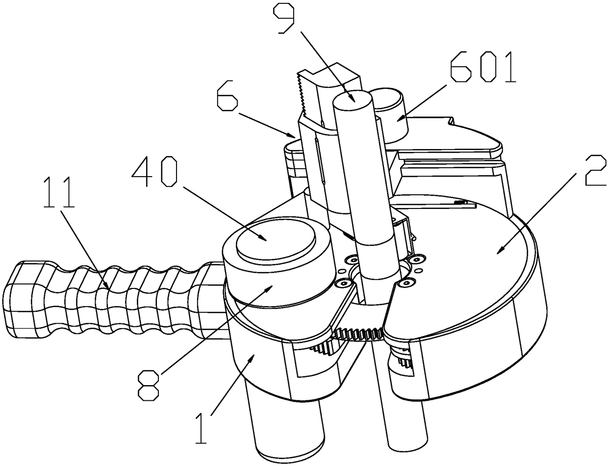
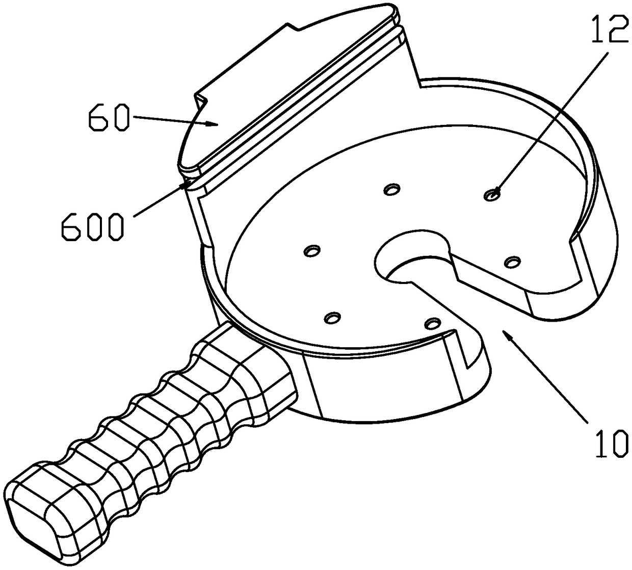
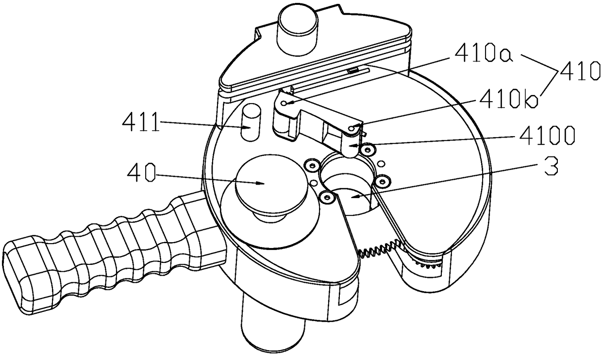
[0053] refer to Figure 1 to Figure 21 The shown portable tape automatic winder mainly includes a hollow cylindrical casing 1, the upper end of which is open, and a mounting plate 2 is provided for its internal rotation, and the mounting plate 2 is coaxially arranged with the casing 1. The casing 1 is provided with a winding drive device 5, which is mainly used to drive the mounting plate 2 to rotate, and its rotation plane is parallel to the open end surface of the casing 1, and the mounting plate 2 is provided with a tape supply device.

[0054] refer to figure 2 , image 3 with Image 6 , the center of the housing 1 and the mounting plate 2 are oppositely provided with a through hole, and the through hole penetrates both sides of the surface at the same time to form a wire harness through hole 3. When in use, the wire harness can pass through the wire ...


PUM


Abstract

The invention discloses a portable automatic adhesive tape winding device which comprises a housing, a mounting plate rotatably arranged in the housing, a wire harness penetrating hole, an adhesive tape supply device and an adhesive tape winding driving device, wherein the wire harness penetrating hole is of a through hole structure penetrating through the housing and the mounting plate simultaneously and is formed in the rotating center of the mounting plate; the adhesive tape supply device comprises an adhesive tape mounting base for placing an adhesive tape roll and a hold-down mechanism capable of extruding the adhesive tape towards the wire harness; the adhesive tape mounting base and the hold-down mechanism are positioned on the mounting plate; and the adhesive tape winding driving device is used for driving the mounting plate to rotate to enable the adhesive tape supply device to do circular motion around a to-be-wound wire harness so as to wind the adhesive tape on the wire harness. With adoption of the structure, the adhesive tape is automatically wound and is compressed, so that the adhesive tape winding quality is improved; after the adhesive tape is wound, the adhesivetape is automatically and completely cut off; the end parts of the adhsive tape are clamped and pulled to a wire harness winding station, so that the initial end of the adhesive tape is wound on the wire harness, the manual operating steps are reduced, the adhesive tape winding efficiency is greatly improved to facilitate improvement of the production efficiency and reduce the manual labor intensity.

Description

technical field [0001] The invention belongs to the technical field of tape winding tools, in particular to a portable automatic tape winder. Background technique [0002] In the process of wire harness production or cable connection, in order to make the wire harness or connecting joints have good insulation properties, insulating tape is usually wrapped outside the wire harness or outside the joints. The traditional method is to use manual winding, that is, first tighten the wire harness and then , and then manually wound one by one, which greatly increases the labor intensity of the workers. At the same time, because each person uses different forces, it will also lead to different standards for the final wound wire harness. , and the manual winding method is used, its work efficiency is low, which greatly affects the production efficiency. Even if some equipment can realize the function of automatic winding, because of its complicated structure, it usually needs manual a...

Claims


Application Information

Patent Timeline
IPC IPC(8): B65H35/04
CPCB65H35/0033
Inventor 伯朝平古猛
Owner 伯朝平
Learn More