Floor expansion joint structure used in complex use environments and construction method thereof

A technology of expansion joints and floors, which is applied to building structures, building components, floors, etc., can solve the problems of prone to staggered platforms, unprotected board edges, and damaged experimental facilities, etc., to achieve convenient construction, waterproof and durable even force effect

Active Publication Date: 2018-08-28
CHINA AVIATION PLANNING & DESIGN INST GRP
View PDF6 Cites 9 Cited by
  • Summary
  • Abstract
  • Description
  • Claims
  • Application Information

AI Technical Summary

Problems solved by technology

[0003] The purpose of the present invention is to provide a technical problem of floor expansion joint structure and construction method used in complex use environment, to solve the inconvenience of concrete pouring in existing sliding dowel type expansion joints, and the quality cannot meet the design requirements The technical problem is to

Method used


Image

  • Floor expansion joint structure used in complex use environments and construction method thereof
  • Floor expansion joint structure used in complex use environments and construction method thereof
  • Floor expansion joint structure used in complex use environments and construction method thereof

Examples


Embodiment Construction

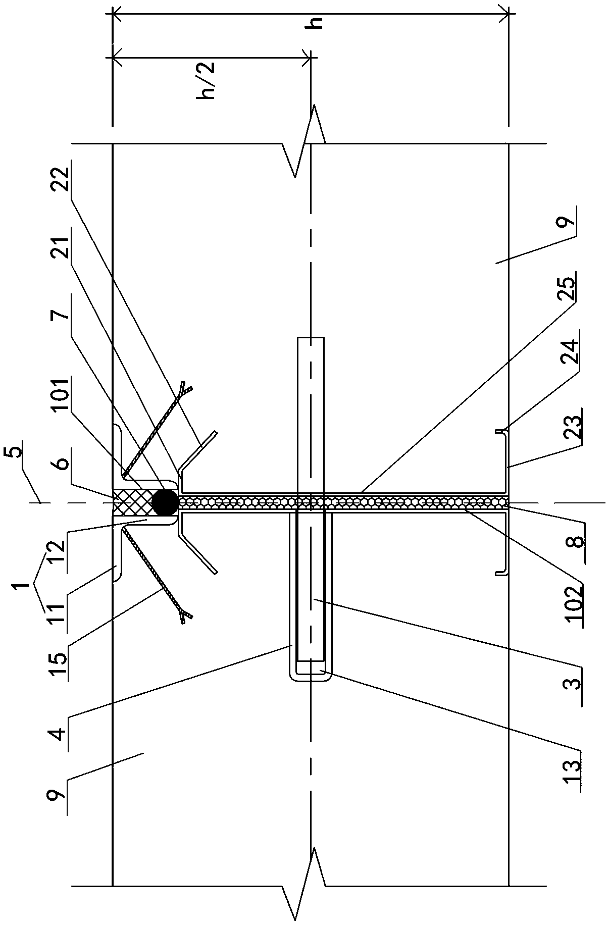
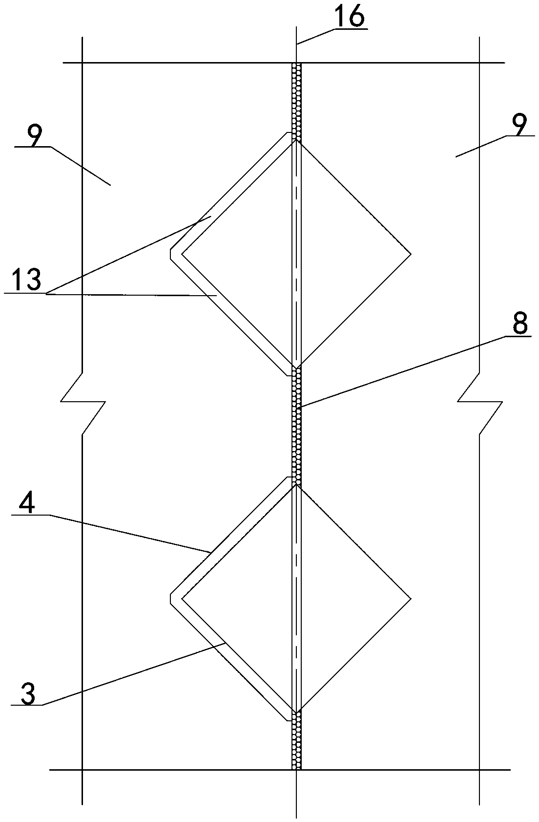
[0040] Examples see Figure 1-3 As shown, a floor expansion joint structure used in a complex use environment includes the floor 9 on both sides and the expansion joint 10 formed between the side end surfaces of the floor.

[0041] The floor expansion joint structure also includes a floor edge-sealing steel structure, an edge-sealing limit structure, an expansion joint waterproof structure, and an expansion joint force transmission structure.

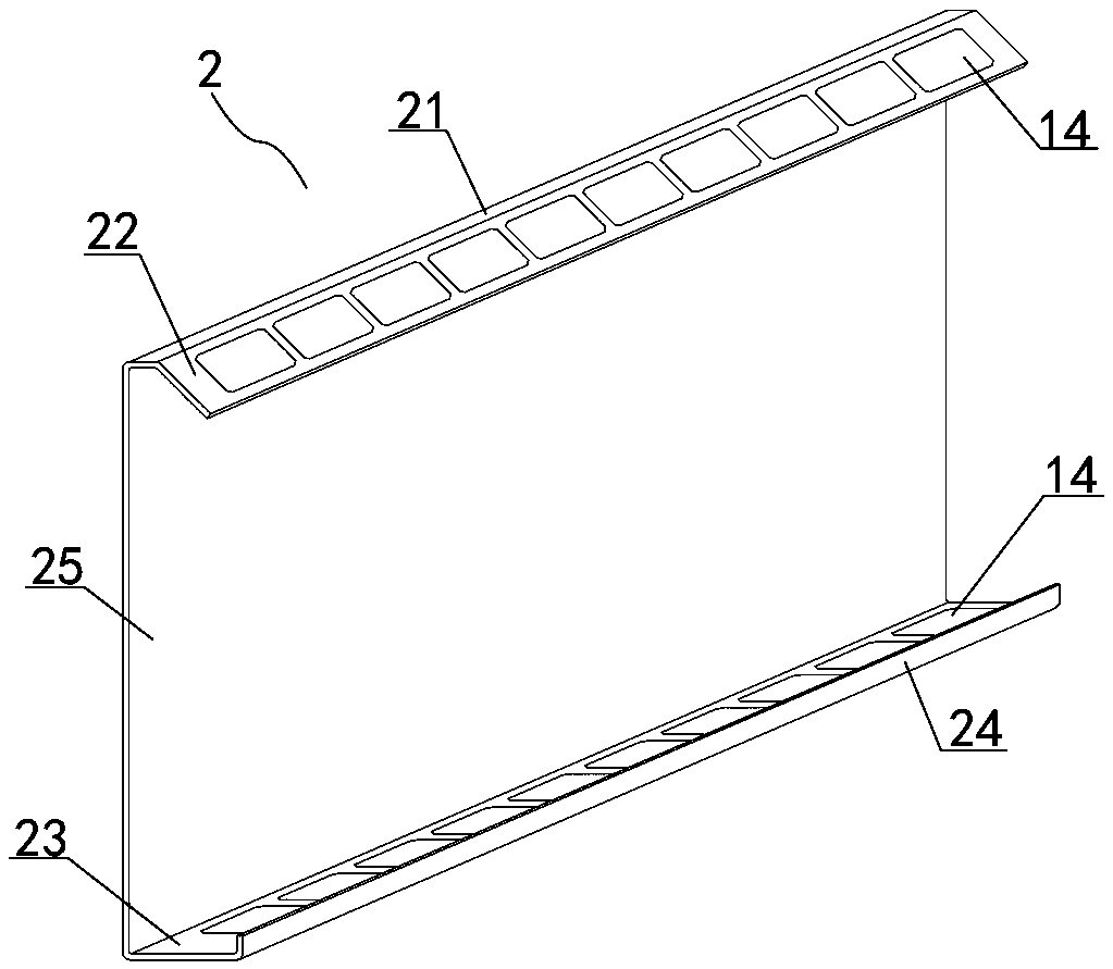
[0042] The floor edge-sealing steel structure is arranged symmetrically along the length direction of the expansion joint, and the floor edge-sealing steel structure is vertically outsourced on the side end faces of the two sides of the floor, including the upper closed angle steel 1 and the lower edge-sealing thin wall Section steel 2.

[0043] The closed angle steel 1 includes a horizontal leg 11 and a vertical leg 12, the upper side of the horizontal leg 11 is flush with the upper side of the ground 9, and the outer side of the vert...


PUM


Abstract

The invention relates to a floor expansion joint structure used in complex use environments. The floor expansion joint structure used in the complex use environments includes floors, an expansion joint, a floor edge sealing steel structure, an expansion joint waterproof structure and an expansion joint force transferring structure. The floor edge sealing steel structure includes closed angle steeland an edge sealing light-gauge steel section, the top of the edge sealing light-gauge steel section supports the bottom end of the closed angle steel, and the top of the edge sealing light-gauge steel section and the bottom end of the closed angle steel are fixedly connected; and the outer side face of the edge sealing light-gauge steel section is flush with the side end faces of the floors at the corresponding positions, and the bottom side face of the edge sealing light-gauge steel section is flush with the lower side faces of the floors. The expansion joint is filled with the expansion joint waterproof structure, and the expansion joint force transferring structure comprises a force transferring steel plate and a force transferring steel plate sleeve. According to the floor expansionjoint structure used in the complex use environments, the floor edge sealing steel structure is designed at the expansion joint of the floors and used as the formwork when concrete is poured on the floors, the convenience and quality of concrete pouring are ensured, and plate joints are prevented from being damaged due to collision; and according to the arrangement of the expansion joint waterproof structure and the expansion joint force transferring structure, the requirements of the deformation, load bearing and durability of the expansion joint in the complex use environments can be met.

Description

technical field [0001] The invention relates to the field of floor expansion joints in industrial building structure design, in particular to an expansion joint structure used in extreme environments and a construction method thereof. Background technique [0002] In the construction floor of industrial plants or laboratories, it is generally required to set up floor expansion joints to prevent concrete shrinkage and temperature changes from causing cracks. For indoor floors, only shrinkage joints are generally provided, including flat joints, tongue and groove joints and false joints. For outdoor floors, expansion joints are required to adapt to deformation caused by temperature changes. For indoor special test plants in complex and extreme environments, the floor is the carrier of various experiments. It is directly exposed to experimental environments including high and low temperature, rain and snow. The drastic changes in cold and hot temperatures will cause deformation...

Claims


Application Information

Patent Timeline
IPC IPC(8): E04B1/68E04F15/14
CPCE04B1/68E04B1/6801E04B1/6804E04B1/6806E04F15/14E04F15/142
Inventor 裴永忠鄂颖男覃杰张广英
Owner CHINA AVIATION PLANNING & DESIGN INST GRP
Why Eureka
Try Eureka