
Oil separator

A technology of oil and gas separator and separator, which is applied in the direction of machine/engine, crankcase ventilation, mechanical equipment, etc., can solve the problem of low separation efficiency, and achieve the effect of improving the separation effect and solving the low separation efficiency.

Inactive Publication Date: 2020-02-14
BORGWARD AUTOMOTIVE CHINA CO LTD
View PDF5 Cites 0 Cited by
  • Summary
  • Abstract
  • Description
  • Claims
  • Application Information

AI Technical Summary

Problems solved by technology

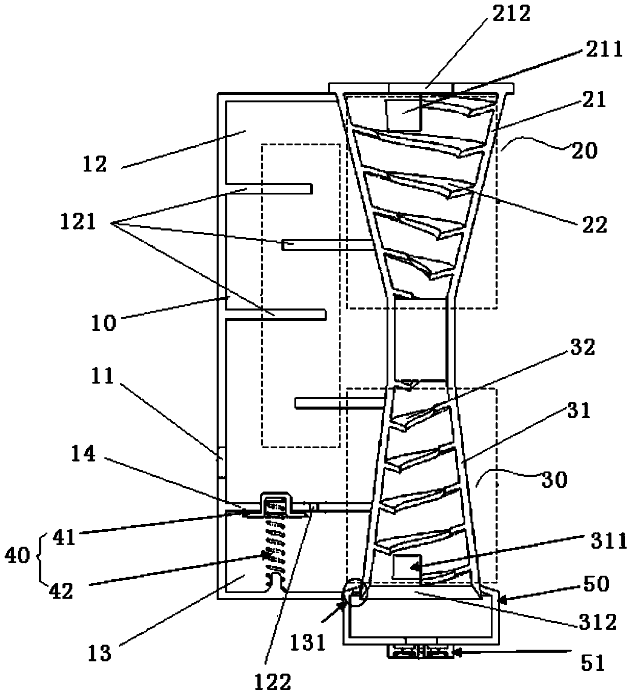
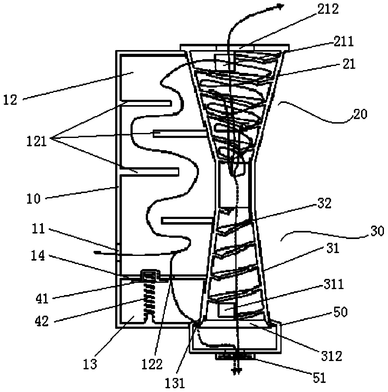
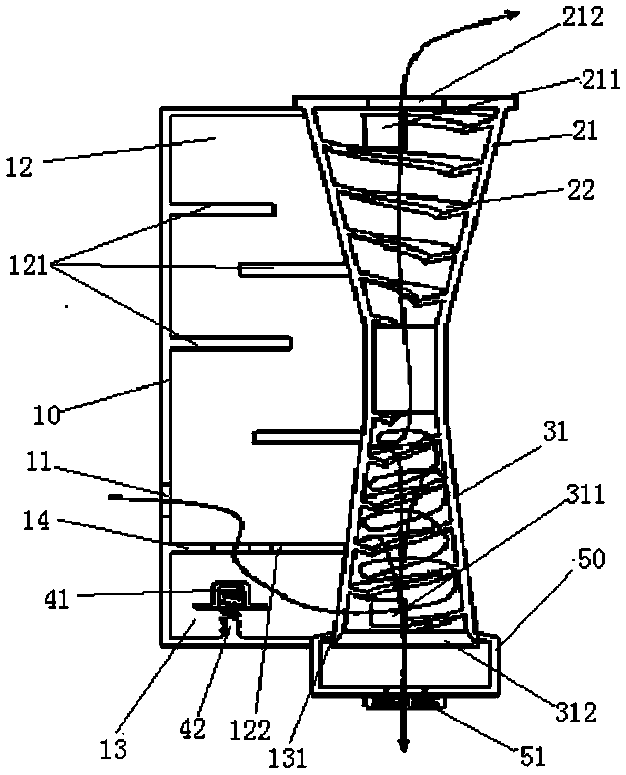
[0004] The invention provides an oil-gas separator to solve the technical problem of low separation efficiency of the oil-gas separator in the prior art

Method used


Image

  • Oil separator
  • Oil separator
  • Oil separator

Examples


Embodiment Construction

[0023] The following will clearly and completely describe the technical solutions in the embodiments of the present invention with reference to the accompanying drawings in the embodiments of the present invention. Obviously, the described embodiments are only some, not all, embodiments of the present invention. The following description of at least one exemplary embodiment is merely illustrative in nature and in no way taken as limiting the invention, its application or uses. Based on the embodiments of the present invention, all other embodiments obtained by persons of ordinary skill in the art without creative efforts fall within the protection scope of the present invention.

[0024] like figure 1 As shown, the embodiment of the present invention provides an oil-gas separator, which includes: a first housing 10, a first separator 20, a second separator 30 and a control valve assembly. Wherein, the first housing 10 has an oil and gas inlet 11 and a first passage 12 and a s...


PUM


Abstract

The invention provides an oil-gas separator. The oil-gas separator comprises a first shell, a first separator, a second separator and a control valve assembly. The first shell is provided with an oil-gas inlet, a first channel and a second channel, wherein the first channel and the second channel are arranged in a spaced manner. The first separator communicates with the first channel. The second separator communicates with the second channel. The control valve assembly is arranged in the first shell, and the oil-gas inlet selectively communicates with the first channel and / or the second channel through the control valve assembly. The first separator and / or the second separator are / is of a spiral separation structure. By means of the provided technical scheme, the technical problem that anoil-gas separator in the prior art is low in separation efficiency can be solved.

Description

technical field [0001] The invention relates to the technical field of automobile engines, in particular to an oil-gas separator. Background technique [0002] When the automobile engine is working, part of the gas in the combustion chamber of the combustion chamber will escape into the crankcase with the reciprocating motion of the piston. These gases generally enter the combustion chamber again through the crankcase ventilation system to participate in combustion and discharge. With the development of engine technology, the particle diameter of engine oil in the crankcase is greatly reduced compared with before, and the crankcase gas is more likely to carry a large number of oil particles out of the crankcase, resulting in high oil consumption. Therefore, an efficient oil-gas separation system is necessary. [0003] In the field of automobile engines, passive oil-gas separators are currently used. Common passive oil-gas separators can be divided into centrifugal, impact a...

Claims


Application Information

Patent Timeline
Patent Type & Authority Patents(China)
IPC IPC(8): F01M13/04
CPCF01M13/04F01M2013/0422F01M2013/0433
Inventor 徐佩东时斗玉
Owner BORGWARD AUTOMOTIVE CHINA CO LTD
Learn More