
Constant-speed winding type winding needle combination mechanism

A combined mechanism and needle winding technology, which is applied in sustainable manufacturing/processing, electrochemical generators, electrical components, etc., can solve the problem that the winding mechanism cannot perform high-speed winding, the peak value of the winding tension curve fluctuates, and the tension cannot be guaranteed, etc. Problems, to achieve the effect of facilitating subsequent processing and production, stable quality, and facilitating the organization to recycle needles

Pending Publication Date: 2018-08-28
GUANGDONG JITI SMART EQUIP CO LTD
View PDF0 Cites 5 Cited by
  • Summary
  • Abstract
  • Description
  • Claims
  • Application Information

AI Technical Summary

Problems solved by technology

[0004] The purpose of the present invention is to provide a constant-speed winding needle combination mechanism to solve the above-mentioned background technology that all the current winding needles for square winding are rectangular, and when the winding needle makes a circular motion around the center, the winding pole The film and the diaphragm will have different circumference lengths formed by each angle when the winding needle rotates, causing the peak value of the winding tension curve to fluctuate greatly, and it is impossible to ensure that the tension is constant within a certain range, so the winding mechanism currently in use cannot perform high-speed winding problem

Method used


Image

  • Constant-speed winding type winding needle combination mechanism
  • Constant-speed winding type winding needle combination mechanism
  • Constant-speed winding type winding needle combination mechanism

Examples


Embodiment Construction

[0014] The following will clearly and completely describe the technical solutions in the embodiments of the present invention with reference to the accompanying drawings in the embodiments of the present invention. Obviously, the described embodiments are only some, not all, embodiments of the present invention. Based on the embodiments of the present invention, all other embodiments obtained by persons of ordinary skill in the art without making creative efforts belong to the protection scope of the present invention.

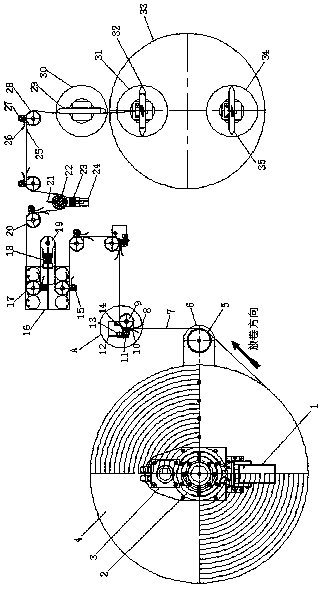
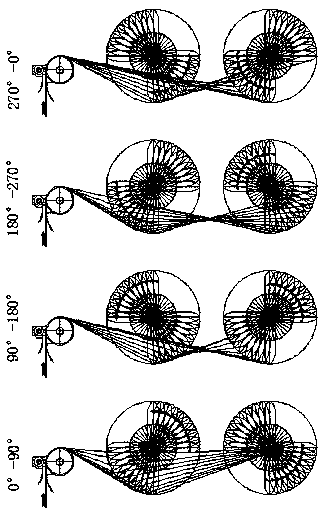
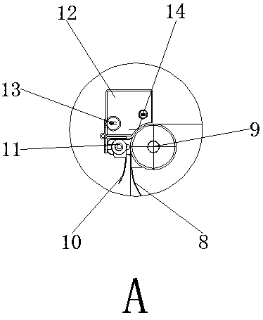
[0015] see Figure 1-3 , the present invention provides a technical solution: a constant-speed winding needle combination mechanism, including an unwinding and deviation-correcting actuator 1, a mechanical shaft expansion mechanism 2 is provided on the top side wall of the unwinding and deviation-correcting actuator 1, and the mechanical shaft expansion mechanism 2 The top side wall is equipped with an unwinding servo motor 3, and the outer wall of the unwindi...


PUM


Abstract

The invention relates to a constant-speed winding type winding needle combination mechanism. The constant-speed winding type winding needle combination mechanism comprises an unwinding correction execution mechanism, wherein a battery pole piece is arranged at the outside wall of an unwinding servo motor; an unwinding passing roll support plate is arranged above a first unwinding passing roll; theoutside wall of the unwinding passing roll support plate is connected with an unwinding pole piece; the top end of the unwinding pole piece is connected with a pole lug flattening plate A of a pole piece passing roll; the pole piece passing roll is arranged at the upper side wall of the pole lug flattening plate A of the pole piece passing roll; a pole lug flattening plate B of the pole piece passing roll is arranged at the left side wall of the pole piece passing roll; a pole lug flattening adjusting mechanism is arranged at the side wall of the top part of the pole lug flattening plate B ofthe pole piece passing roll; a pole piece dedusting mechanism is arranged above the pole lug flattening adjusting mechanism. The constant-speed winding type winding needle combination mechanism has the advantages that the winding speed is effectively improved; a battery cell is wound within constant tension value; the looseness of the inner layer and outer layer of the battery cell is uniform; the quality of the wound finished product battery cell is stable; the efficiency is improved by one time or more; the winding speed can reach 1400mm / s.

Description

technical field [0001] The invention belongs to the technical field of battery manufacturing, and in particular relates to a winding needle combination mechanism of a winding machine. Background technique [0002] Lithium-ion battery is a new type of high-energy battery successfully developed in the 20th century. Lithium-ion research began in the 1980s, entered the stage of industrialization in the 1990s, and developed rapidly. Lithium-ion batteries are favored by various industries due to their high specific energy, small size, and environmental friendliness. They are widely used in mobile phones, laptops and other digital products and new energy vehicles. [0003] In the winding process of the battery cell winding manufacturing process, all the winding needles for square winding are rectangular. When the winding needle makes a circular motion around the center, the wound pole piece and diaphragm will be rotated by the winding needle. When the length of the circle formed ...

Claims


Application Information

Patent Timeline
IPC IPC(8): H01M10/0587
CPCH01M10/0587Y02E60/10Y02P70/50
Inventor 张祥领
Owner GUANGDONG JITI SMART EQUIP CO LTD
Learn More