Method for producing high-pressure pipe

A technology of inner tube and outer tube, applied in the direction of pipe, rigid tube, pipeline protection, etc., can solve the problem of frequent replacement, etc., and achieve the effect of high protection, strength, increase in size and surface quality, and increase in compression resistance

Pending Publication Date: 2018-08-28
SANDVIK MATERIALS TECH DEUTLAND
View PDF10 Cites 1 Cited by
  • Summary
  • Abstract
  • Description
  • Claims
  • Application Information

AI Technical Summary

Problems solved by technology

With the same type of construction, this has the result that the components subjected to dynamic pressure wear out more quickly and have to be replaced more frequently than in the case of components subjected to static pressure

Method used


Image

  • Method for producing high-pressure pipe
  • Method for producing high-pressure pipe
  • Method for producing high-pressure pipe

Examples


Embodiment Construction

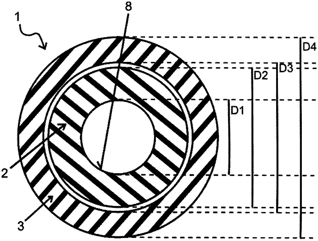
[0047] FIG. 1 shows a schematic cross-sectional view of the outer tube 3 and the inner tube 2 extending in the outer tube 3 . The inner tube 2 has a first inner diameter D1 and a first outer diameter D2, while the outer tube 3 has a second inner diameter D3 and a second outer diameter D4, wherein the first outer diameter D2 is smaller than the second inner diameter D3.

[0048] The inner tube 2 consists of raw material HP 160, which is a high-strength nitrogen-alloyed austenitic stainless steel with high corrosion resistance. The inner tube 2 is here produced in a periodic rolling mill by rolling a tube blank made of metal over rolling mandrels. To carry out the rolling movement, two work rolls mounted rotatably on shafts are located in reciprocating roll stands. The work rolls are driven here by the reciprocating movement of the roll holders. The tube blanks arranged between rotating work rolls are rolled on tapering rolling mandrels and undergo a gradual infeed after each ...


PUM

PropertyMeasurementUnit
Tensile strengthaaaaaaaaaa

Abstract

The invention relates to a method for producing a high-pressure pipe (1). An inner pipe (2) made of metal and an outer pipe (3) made of metal are drawn together through a first drawing die (4a). The outer diameter (D2) of the inner pipe is smaller than the inner diameter (D3) of the outer pipe. By drawing the outer pipe and the inner pipe, which extends in the outer pipe, together through the first drawing die, a very stable force-fitting connection is produced between the inner pipe and the outer pipe. As a result, a pipe is produced with a large wall thickness, by means of which the producedpipe is very robust and pressure-resistant while having a very high quality outer lateral surface and in particular a very high quality inner lateral surface by virtue of the cold forming process. These two properties allow a sufficiently high protection of the pipe to be produced against bursting when pressures in excess of 12,000 bar are applied to the pipe. Accordingly, the method according tothe invention is particularly suitable for producing a pipe with clearly improved dynamic pressure resistance against high pressures by combining a large wall thickness of the pipe to be produced with a high quality inner lateral surface of the pipe to be produced.

Description

technical field [0001] The invention relates to a method for producing a tube. Background technique [0002] In many technical fields, such as, for example, fuel injection technology for internal combustion engines and the chemical industry, pipelines are used which are subjected to high pressure and must withstand this pressure for a long time. A distinction is made here between the static pressure load of the line (ie, a temporally and spatially constant pressure load) and the hydrodynamic load of the line (ie, a temporally and / or spatially varying pressure load). In many technical fields of application, pressure-carrying components are subjected to temporally and spatially varying, and in some cases also periodically pulsating, pressure loads, so that they have significantly higher demands than statically loaded components, depending on the load class. or pressure load capacity. With the same construction type, this has the result that the components subjected to dynami...

Claims


Application Information

Patent Timeline
IPC IPC(8): B21C37/15B21C1/22
CPCB21C37/154B21C1/22F16L9/147F16L57/02F16L58/08
Inventor 克里斯托弗·赫德瓦尔乌多·劳夫曼托马斯·弗罗伯泽
Owner SANDVIK MATERIALS TECH DEUTLAND
Why Eureka
Try Eureka