Electromagnet clamping, positioning, and rotating mechanism used for auto spare part board

A technology for clamping and positioning and auto parts, which is applied in the direction of conveyors, conveyor objects, metal processing, etc., can solve problems such as troublesome and low efficiency, and achieve the effect of high efficiency, good effect, and convenient automatic processing

Inactive Publication Date: 2018-08-31
DONGGUAN SHENGRONG AUTOMATION TECH CO LTD
View PDF6 Cites 12 Cited by
  • Summary
  • Abstract
  • Description
  • Claims
  • Application Information

AI Technical Summary

Problems solved by technology

[0002] When the existing auto parts board is processed, it needs to be turned over, and the existing method is generally manual turning, which is very troublesome and inefficient

Method used


Image

  • Electromagnet clamping, positioning, and rotating mechanism used for auto spare part board
  • Electromagnet clamping, positioning, and rotating mechanism used for auto spare part board

Examples


Embodiment Construction

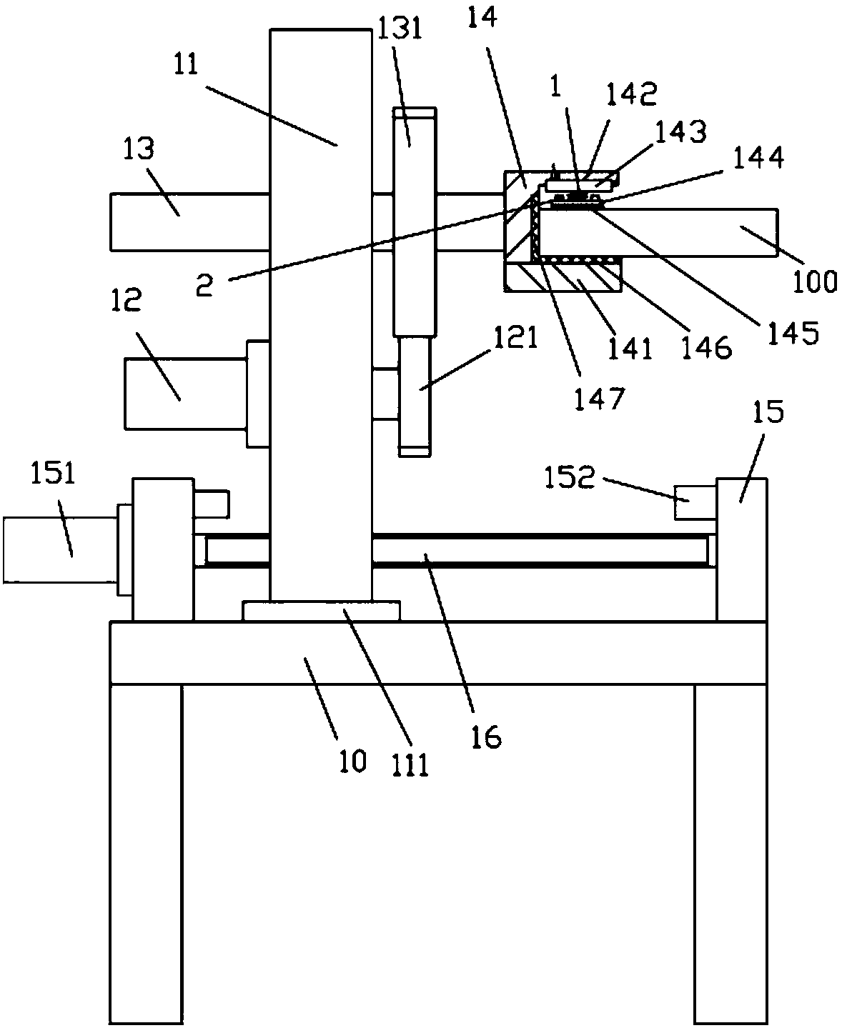
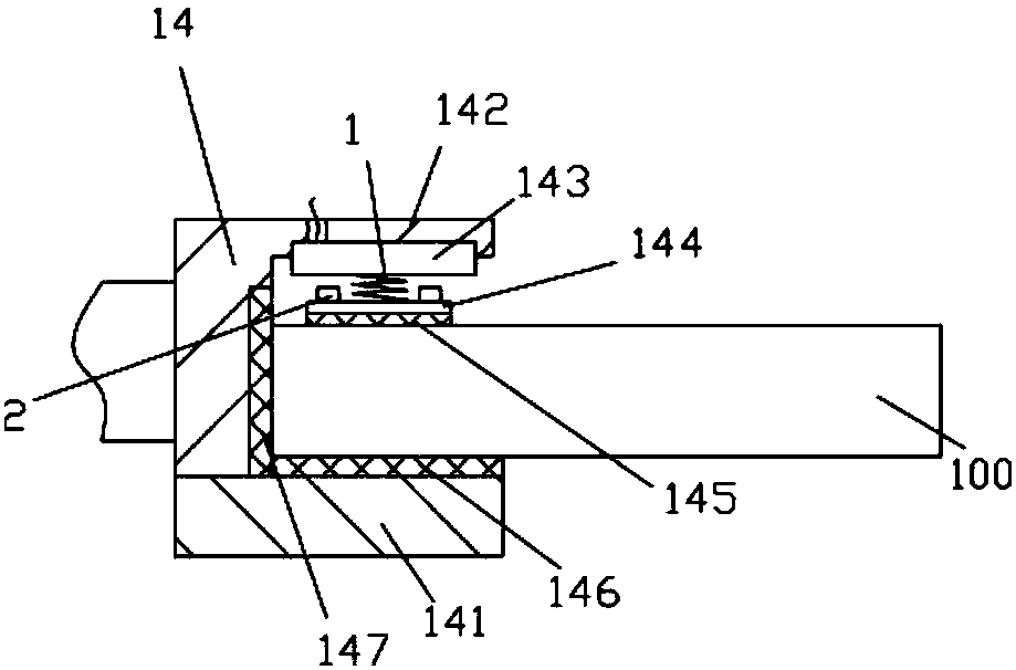
[0013] Examples, see e.g. Figure 1 to Figure 2 As shown, a kind of auto parts plate body uses electromagnet clamping positioning rotation mechanism, comprises frame 10, and the two sides of the top surface of the top plate of described frame 10 are fixed with mobile supporting plate 15, and the two ends of transverse screw rod 16 are hinged on On the two mobile support plates 15, a mobile motor 151 is fixed on the outer wall of one of the mobile support plates 15. The output shaft of the mobile motor 151 is a spline shaft, and the spline shaft is inserted into the spline at one end of the transverse screw rod 16. In the hole, the vertical support plate 11 is screwed in the horizontal screw rod 16, the bottom of the left side wall of the vertical support plate 11 is fixed with a drive servo motor 12, and the output shaft of the drive servo motor 12 passes through the vertical support plate 11 and is fixed. Drive gear 121 is arranged, and the top of vertical supporting plate 11...


PUM


Abstract

The invention discloses an electromagnet clamping, positioning, and rotating mechanism used for auto spare part boards. The mechanism comprises a rack. Two sides of a top plate top surface of the rackare fixedly provided with movable supporting plates. Two ends of a horizontal screw are hinged with the two movable supporting plates. The outer side wall of one of the movable supporting plates is fixedly provided with a moving motor. An output shaft of the moving motor is a spline shaft. The spline shaft is inserted in a spline hole on one end of the horizontal screw. A vertical supporting plate is screwed in the horizontal screw. The lower part of the left side wall of the vertical supporting plate is fixedly provided with a drive servo motor. An output shaft of the drive servo motor passes through the vertical supporting plate and is fixedly provided with a driving gear. The upper part of the vertical supporting plate is hinged with a rotating shaft. The right end of the rotating shaft extends out of the vertical supporting plate and is fixedly provided with a clamping plate. The rotating shaft is fixedly provided with a transmission gear. The electromagnet clamping, positioning,and rotating mechanism can automatically clamp an auto spare part board and automatically turn over the auto spare part board, providing convenience for subsequent equipment to grab the auto spare part board and perform automated processing. The mechanism is good in effect and high in efficiency.

Description

Technical field: [0001] The invention relates to the technical field of automobile mold processing equipment, and more specifically relates to an electromagnet clamping, positioning and rotating mechanism for an automobile accessory plate. Background technique: [0002] When the existing auto parts board is processed, it needs to be turned over, and the existing method is generally manual turning, which is very troublesome and inefficient. Invention content: [0003] The purpose of the present invention is to overcome the deficiencies of the prior art and provide an electromagnet clamping and positioning rotation mechanism for the auto parts board, which can automatically clamp and turn over the auto parts board to facilitate subsequent equipment grabbing Automatic processing has good effect and high efficiency. [0004] The scheme that the present invention solves described technical problem is: [0005] An auto parts plate body uses an electromagnet to clamp and positi...

Claims


Application Information

Patent Timeline
Patent Type & Authority Applications(China)
IPC IPC(8): B65G47/92B23Q7/00
CPCB65G47/92B23Q7/00B65G2201/0214
Inventor 李胜利
Owner DONGGUAN SHENGRONG AUTOMATION TECH CO LTD
Why Eureka
Try Eureka