Method and system for reworking composite laminate and automated tape placement machine

A composite material layer, composite material technology, used in the field of reprocessing composite material laminates and systems and automatic tape laying machines

Pending Publication Date: 2020-04-28
AIRBUS OPERATIONS SL
View PDF4 Cites 2 Cited by
  • Summary
  • Abstract
  • Description
  • Claims
  • Application Information

AI Technical Summary

Problems solved by technology

[0006] Despite the high degree of automation in tape placement, when a defect is discovered during or after l

Method used


Image

  • Method and system for reworking composite laminate and automated tape placement machine
  • Method and system for reworking composite laminate and automated tape placement machine
  • Method and system for reworking composite laminate and automated tape placement machine

Examples


Embodiment Construction

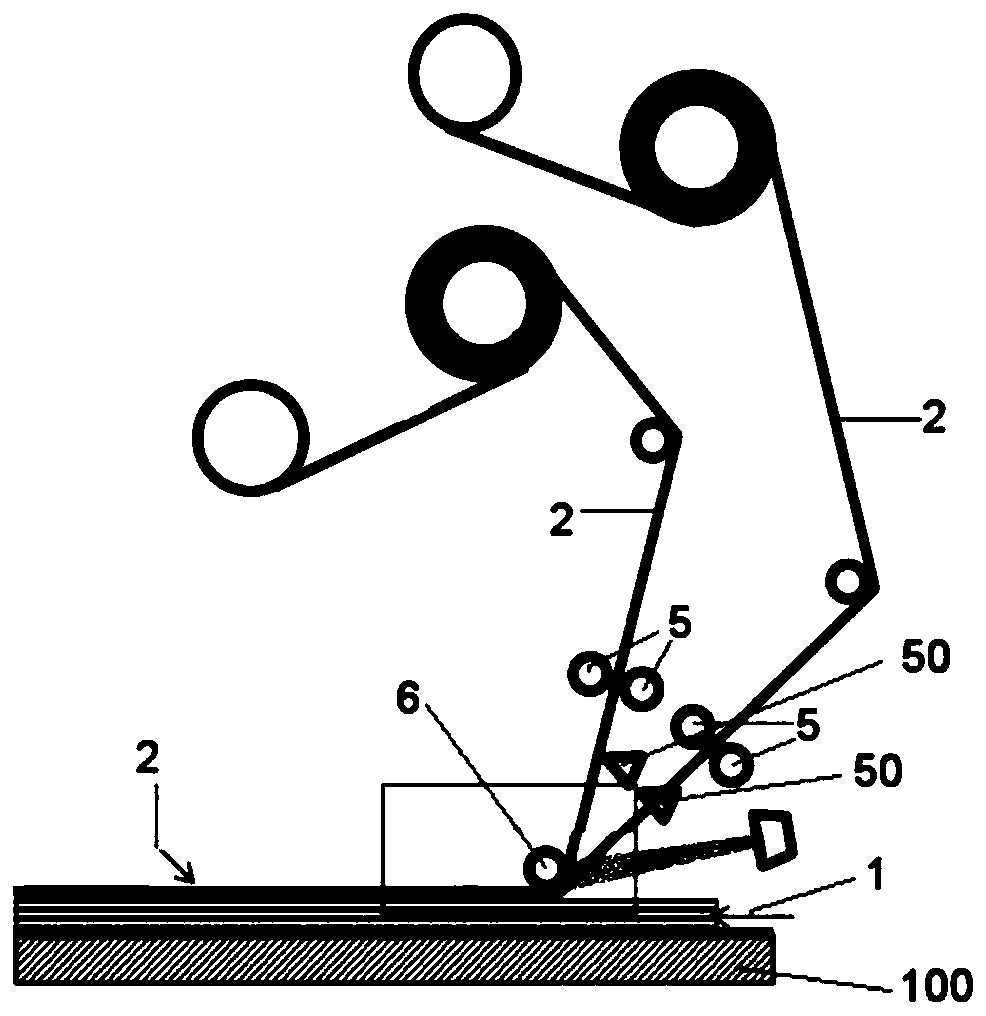
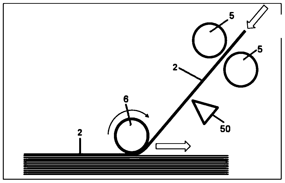
[0041] figure 1 A known automatic tape laying machine is disclosed which passes the lamination tape 2 through the lamination tape 2 by means of two heads comprising at least a pressure roller 6 , an additional roller 5 and a cutter 50 to produce a laminate 1 on a mold 100 . exist figure 2 , the belt 2 is clamped with additional rollers 5 and cut with a blade or other system to end the layup.

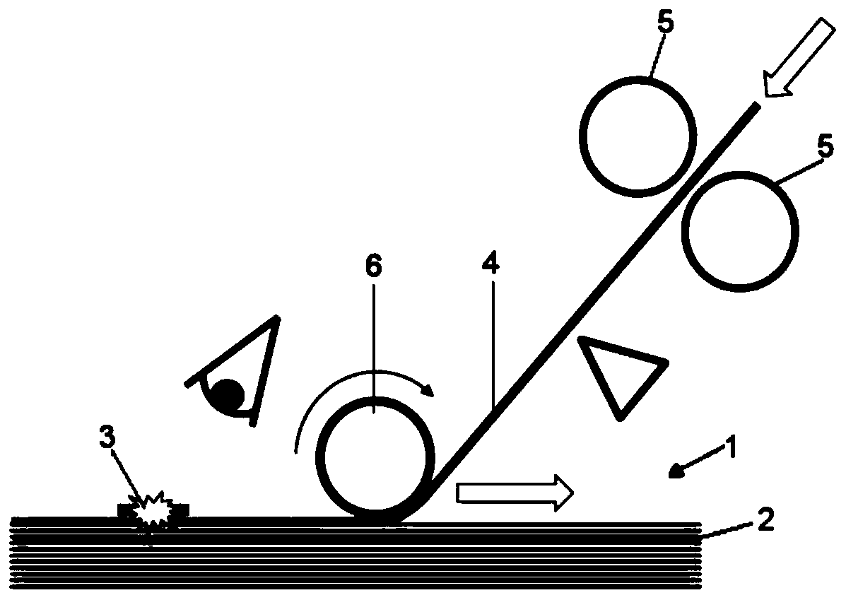
[0042] image 3 The detection of a defect 3 on the strip 4 during laying of the strip 4 is shown. Then, if Figure 4 Laying of the defective strip 4 continues as shown until the strip 4 exceeds the production length L of the strip 4 . By rotation of the additional roller 5, the defective belt 4 is placed between the pressure roller 6 and the laying surface to continue the laying operation.

[0043] In a multi-head machine, when laying multiple strips 2, all strips 2 except the defective strip 4 are laid and cut according to the original designed length of the part, and the defecti...


PUM


Abstract

The invention relates to a method and system for reworking a composite laminate and an automated tape placement machine. In one aspect, a method is provided for reworking a composite laminate (1) comprising a plurality of tapes (2), the method comprising the following steps: detecting the occurrence of a defect (3) on a tape (4) of composite material while the tape (4) is being laid up; continuingthe lay-up of the defective tape (4) until a tape (4) length which surpasses a manufacturing length (L) of the tape (4); catching the part of the defective tape (4) that surpasses the manufacturing length (L) of the tape (4); cutting the defective tape (4) in the part of the defective tape (4) that surpasses the manufacturing length (L) of the tape (4); removing from the laminate (1) the caught defective tape (4) by the catching system, and laying-up a replacement tape (2) in the place of the removed defective tape (4).

Description

technical field [0001] The present invention relates to the automatic manufacture of fiber reinforced composite laminates by using automatic tape laying or wire laying machines. The invention applies to all parts of the structure of an aircraft or any composite material part outside the field of aeronautics. Background technique [0002] Laminates comprising multiple layers of composite material are known which are laid by an automatic tape laying machine comprising a laying head which lays one or more tapes on each track of the laying head . The multiple strips laid on the track are often referred to as pavement. [0003] Today, the manufacturing process of fiber-reinforced plastic parts, commonly referred to as composite parts, is highly automated through the use of tape-laying machines, both in the case of resin-impregnated tapes and dry tapes. figure 1 is a schematic diagram showing the end effector of a typical tape laying machine with two laying heads. [0004] In ...

Claims


Application Information

Patent Timeline
IPC IPC(8): B29C70/38B29C70/34
CPCB29C70/386B29C70/34B29C70/388B29C70/54B29C70/545B29C2793/0081B32B43/00B32B5/26B32B2041/04B32B2260/021B32B2260/046B32B2305/08B32B2605/18B29C73/12
Inventor 乔斯·马努埃尔·梅嫩德斯马丁劳尔·阿尔贝托·卡巴纳斯孔特勒拉佩德罗·卡夫雷拉罗德里格斯
Owner AIRBUS OPERATIONS SL
Why Eureka
Try Eureka