Eureka AIR delivers breakthrough ideas for toughest innovation challenges, trusted by R&D personnel around the world.

Low pressure rear cylinder water spray hole of turbine and design method of low pressure rear cylinder water spray hole

A design method and spray hole technology, applied to cylinders, cylinder heads, mechanical equipment, etc., can solve the problems of increased desuperheating water volume, weak atomization degree of water droplets, and high impact velocity, so as to reduce the incident velocity, expand the diffusion range, Improves the effect of turbulent mixing

Pending Publication Date: 2018-08-31
XIAN XIRE ENERGY SAVING TECH +1
View PDF6 Cites 0 Cited by
  • Summary
  • Abstract
  • Description
  • Claims
  • Application Information

AI Technical Summary

Problems solved by technology

However, the structure of the circular cross-section orifice has technical defects such as high impact velocity of incident water droplets, small diffusion area of ​​water droplets, and weak degree of atomization of water droplets. The amount of desuperheating water increases, and the loss of high-quality desalination condensate water is too high

Method used


Image

  • Low pressure rear cylinder water spray hole of turbine and design method of low pressure rear cylinder water spray hole
  • Low pressure rear cylinder water spray hole of turbine and design method of low pressure rear cylinder water spray hole
  • Low pressure rear cylinder water spray hole of turbine and design method of low pressure rear cylinder water spray hole

Examples


Embodiment Construction

[0019] The present invention will be further described below in conjunction with the accompanying drawings.

[0020] see Figure 5 , the water spray orifice 8 of the low-pressure rear cylinder of the steam turbine is installed and fixed in the upper exhaust guide ring 7 at the outlet of the final stationary blade 5 and the final movable blade 6, arranged along the entire circumference, and the cooling water is sent through the water distribution pipe into the spout.

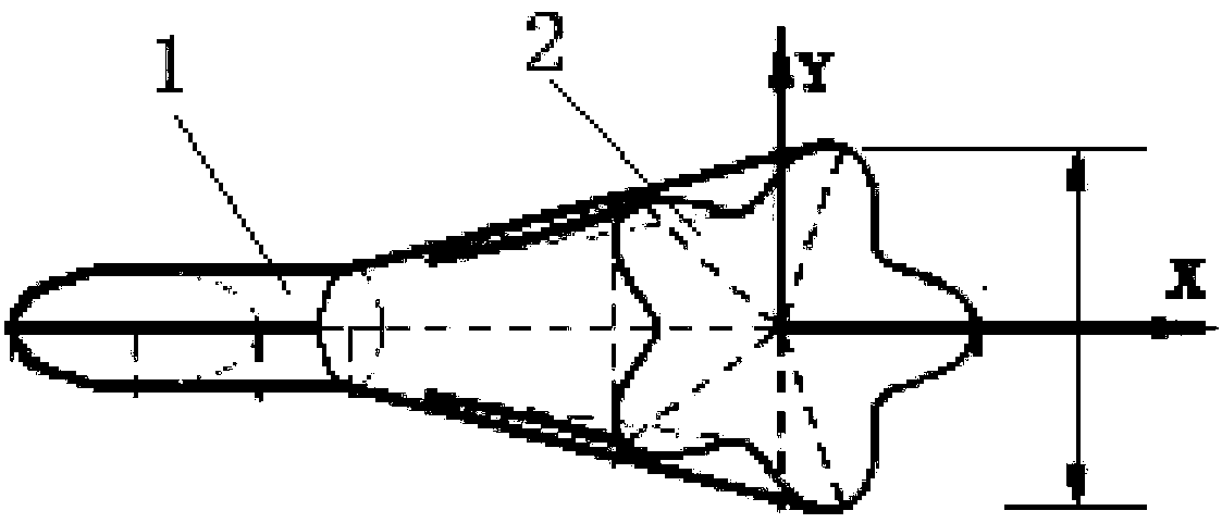
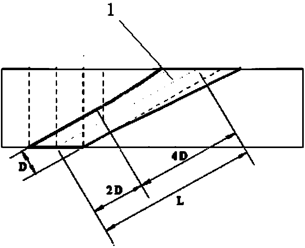
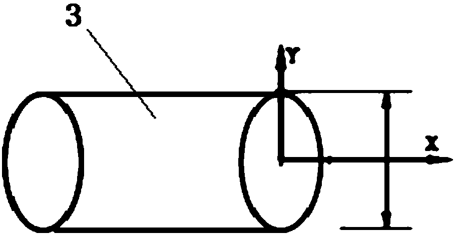
[0021] see figure 1 and figure 2 , a water spray orifice of a low-pressure rear cylinder of a steam turbine, comprising a gradually expanding channel 1 connected to the water spray orifice of the rear cylinder, a water spray port 2 connected to the large end of the gradually expanding channel 1, and the cross section of the water spray port 2 It is star-shaped, the front section of the gradual expansion channel 1 is involute, and the rear section is an inclined channel. The section of the inclined channel gra...


PUM


Abstract

The invention discloses a low pressure rear cylinder water spray hole of turbine and a design method of the low pressure rear cylinder water spray hole. According to the invention, a traditional roundwater spray hole water outlet is changed to a variable section star shape. After incoming water drops pass through the star-shaped hole, the expansion range is enlarged, so that mutual mixture of theincoming water drops and high temperature discharged steam is enhanced. At the same time, local gradually expanding treatment is performed on an inclined channel of the incoming hole and optimizationis performed on the inclination angle of the channel, so that the incoming speed of the incoming water drops decrease after passing through the channel and the incoming position becomes more adjacentto a high temperature area, and the turbulent mixing of the water drops and the high temperature discharge steam is improved further. Through a method of expanding the expansion range of the incomingwater drops in the air cylinder, reducing the incoming speed of the water drops and ensuring the proper direct spray direction of the water drops, requirements for high-efficiency mixture of the water drops and the high temperature discharged steam are met and aims of improving performance of a water spray system and improving the low pressure tail stage safety and stability are achieved.

Description

technical field [0001] The invention belongs to the field of water spray ports of steam turbines, and in particular relates to a water spray port of a low-pressure rear cylinder of a steam turbine and a design method thereof. Background technique [0002] At present, affected by factors such as power peak regulation, thermal power steam turbine units often operate under partial load conditions. As the load rate of the unit decreases, the steam inlet parameters of the low-pressure cylinder of the steam turbine decrease accordingly, and the volumetric flow rate is greatly reduced. Studies have shown that when the unit is operated under the condition of small volume flow, the original aerodynamic design flow field will be destroyed, the thermal parameters of the final stage dynamic and static blades along the blade height will be redistributed, and a large-scale backflow vortex will be formed in the blade tip area. At the same time, the airflow will no longer push the blades t...

Claims


Application Information

Patent Timeline
Patent Type & Authority Applications(China)
IPC IPC(8): F02F1/10
CPCF02F1/10
Inventor 高庆居文平余小兵张永海薛朝囡王妍
Owner XIAN XIRE ENERGY SAVING TECH
Why Eureka
Eureka Blog
Learn More