Microchannel reactor for enhacing multiphase flow heat and mass transfer in microchannel
A technology of microchannel reactor and microchannel, which is applied in chemical/physical/physicochemical reactors, chemical instruments and methods, chemical/physical processes, etc., can solve the problem that fluid movement state is difficult to achieve precise control, and achieve improvement Effects of heat and mass transfer performance, increased contact area, and increased velocity pulsation intensity
- Summary
- Abstract
- Description
- Claims
- Application Information
AI Technical Summary
Problems solved by technology
Method used
Image
Examples
Embodiment 1
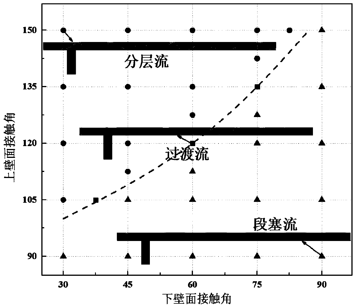
[0050] Embodiment one: the upper coating is a hydrophobic coating, the contact angle of the hydrophobic coating is A1, the lower coating is a hydrophilic coating, and the contact angle of the hydrophilic coating is A2, The value range of A1 is 90 o -150 o , the value range of A2 is 30 o -90 o , and A1-A2o .
[0051] When the upper coating is a hydrophobic coating and the lower coating is a hydrophilic coating, the distribution of the contact angle is as follows: Figure 2a As shown, the multiphase flow manifolds under different combinations of upper and lower wall surface contact angles can be mainly divided into three types: slug flow, transition flow and stratified flow. The results are as follows Figure 2b (The figure also shows a schematic diagram of the shape changes of the bubbles at the three numerical points as indicated by the arrows). Among them, in the transitional flow and stratified flow, the separated bubbles will re-aggregate, thereby reducing the contact ...
Embodiment 2
[0054] Embodiment 2: The mixing channel is sequentially divided into a formation zone, a transition zone and a stable zone from the side where the liquid channel is located; wherein the formation zone and the transition zone are both 900 meters long. μm .
[0055] The upper coating is a hydrophobic coating, and the lower coating is a hydrophilic coating;
[0056] The contact angles of the hydrophobic coating in the formation zone are B1, and the contact angles of the hydrophilic coating are B2; the contact angles of the hydrophobic coating in the stable zone are B3, and the contact angles of the hydrophilic coating are B4;
[0057] The value range of B1 is 90 o -150 o , the value range of B2 is 30 o -90 o ;B3=B4=90 o ;
[0058] The contact angle of the hydrophobic coating in the transition zone varies linearly from B1-B3, and the contact angle of the hydrophilic coating in the transition zone varies linearly from B2-B4.
[0059] In this embodiment, the distribution of ...
Embodiment 3
[0060] Embodiment 3: The upper coating is composed of hydrophobic coating and hydrophilic coating alternately, and is firstly hydrophobic coating from the side where the liquid channel is located;
[0061] The undercoat layer is composed of hydrophobic coatings and hydrophilic coatings alternately, and is firstly a hydrophilic coating from the side where the liquid channel is located;
[0062] The contact angle of the hydrophobic coating in the upper coating and the lower coating is C1, the contact angle of the hydrophilic coating in the upper coating and the lower coating is C2, and the value range of C1 is 90 o -150 o , the value range of C2 is 30 o -90 o , and C1-C2o .
[0063] In this embodiment, the upper and lower walls of the microchannel are divided into 7 equally spaced subsections, each of which is twice the length of the channel width, and each subsection is respectively set as a hydrophilic or hydrophobic coating in an alternately changing form to ensure that th...
PUM
 Abstract
Description
Claims
Application Information
 - R&D
- Intellectual Property
- Life Sciences
- Materials
- Tech Scout
- Unparalleled Data Quality
- Higher Quality Content
- 60% Fewer Hallucinations
Browse by: Latest US Patents, China's latest patents, Technical Efficacy Thesaurus, Application Domain, Technology Topic, Popular Technical Reports.
© 2025 PatSnap. All rights reserved.Legal|Privacy policy|Modern Slavery Act Transparency Statement|Sitemap|About US| Contact US: help@patsnap.com


