
Two-stage compression piston type air compressor crankcase rear end heavy hammer air valve air return path structure

A two-stage compression and air compressor technology, which is applied to liquid variable-capacity machinery, mechanical equipment, and variable-capacity pump components, etc. problems, to achieve the effect of eliminating the fracture and damage of the crankshaft, reducing the starting torque and reducing the power consumption

Pending Publication Date: 2018-08-31
盐城中德劲博机电有限公司
View PDF0 Cites 0 Cited by
  • Summary
  • Abstract
  • Description
  • Claims
  • Application Information

AI Technical Summary

Problems solved by technology

[0002] The head of the two-stage compression piston air compressor is installed in the working system of the whole machine. When the whole machine cannot be powered off normally or shut down manually, the air pressure switch in the air circuit control element will appear abnormal action. At this time It will cause the high-pressure gas in the exhaust pipe of the whole machine to not be emptied, and the pressurized air trapped in the exhaust pipe will cause the piston air compressor to start again under load instead of no-load. The starting torque of the whole air compressor is increased, and the input power is increased, which is likely to cause the risk of crankshaft fracture and damage due to the force on the crankshaft exceeding the design capacity. How to design an auxiliary structure that can discharge the compressed air in the exhaust pipe in time has become a problem for people Issues that urgently need to be resolved

Method used


Image

  • Two-stage compression piston type air compressor crankcase rear end heavy hammer air valve air return path structure
  • Two-stage compression piston type air compressor crankcase rear end heavy hammer air valve air return path structure
  • Two-stage compression piston type air compressor crankcase rear end heavy hammer air valve air return path structure

Examples


Embodiment Construction

[0010] The specific content of the present invention will be described in detail below in conjunction with the accompanying drawings and specific embodiments.

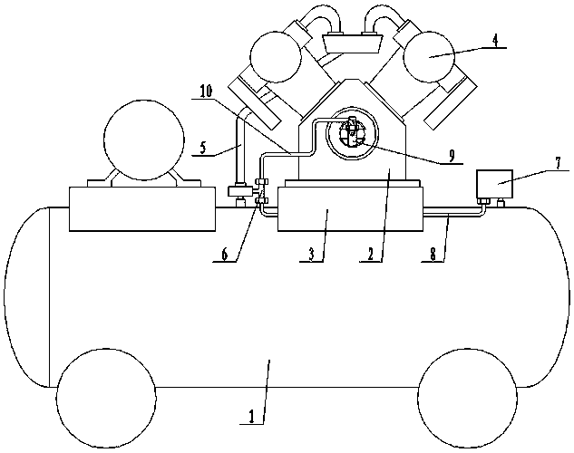
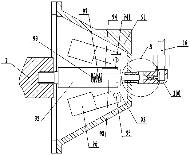
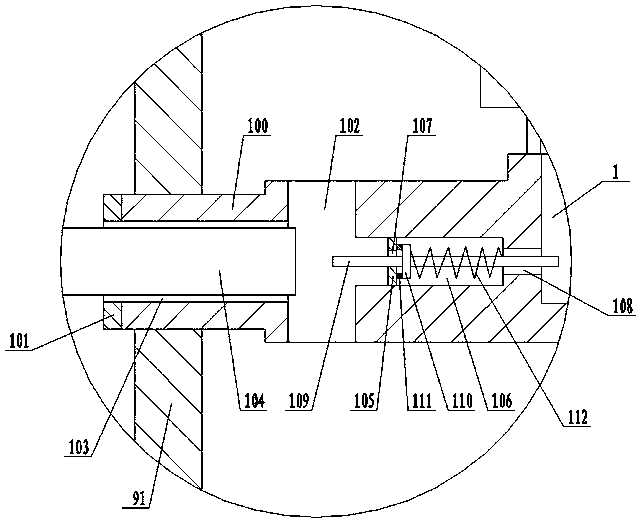
[0011] Such as figure 1 , figure 2 , image 3 As shown, the structure of the air return path of the heavy hammer valve at the rear end of the crankcase of the two-stage compression piston air compressor includes: the main body of the air compressor 1, and the crankcase 2 is installed on the main body 1 of the air compressor through the mounting seat 3. Both sides of the upper end of the crankcase 2 are provided with a cylinder 4, the cylinder 4 is connected with the air compressor main body 1 through an exhaust pipe 5, and a tee joint 6 communicating with it is provided on the exhaust pipe 5, An air pressure switch 7 is arranged on the main body 1 of the air compressor, and the air pressure switch 7 is connected to the three-way joint 6 through the main pipe 8 of the exhaust pipe, and a heavy hammer air valve is arr...


PUM


Abstract

The invention discloses a two-stage compression piston type air compressor crankcase rear end heavy hammer air valve air return path structure. The two-stage compression piston type air compressor crankcase rear end heavy hammer air valve air return path structure comprises an air compressor body. A crankcase is arranged on the air compressor body through an installing base. Air cylinders are arranged on the two sides of the upper end of the crankcase and connected with the air compressor body through an exhaust pipe. The exhaust pipe is provided with a three-way connector communicating with the exhaust pipe. The air compressor body is provided with an air pressure switch. The air pressure switch is connected with the three-way connector through an exhaust pipe emptying main pipeline. Thecrankcase is provided with a heavy hammer air valve. The heavy hammer air valve is connected with the three-way connector through an exhaust pipe emptying auxiliary pipeline. The heavy hammer air valve structurally comprises a heavy hammer air valve machine base connected with the crankcase, and a rotation shaft is rotationally arranged in the heavy hammer air valve machine base.

Description

technical field [0001] The invention relates to an air compressor, in particular to a return air path structure of a heavy hammer air valve at the rear end of a crankcase of a two-stage compression piston type air compressor. Background technique [0002] The head of the two-stage compression piston air compressor is installed in the working system of the whole machine. When the whole machine cannot be powered off normally or shut down manually, the air pressure switch in the air circuit control element will appear abnormal action. At this time It will cause the high-pressure gas in the exhaust pipe of the whole machine to not be emptied, and the pressurized air trapped in the exhaust pipe will cause the piston air compressor to start again under load instead of no-load. The starting torque of the whole air compressor is increased, and the input power is increased, which is likely to cause the risk of crankshaft fracture and damage due to the force on the crankshaft exceedin...

Claims


Application Information

Patent Timeline
IPC IPC(8): F04B39/10F04B49/03
CPCF04B39/10F04B49/03
Inventor 卞兴志陈泽徐云
Owner 盐城中德劲博机电有限公司
Features
  • Generate Ideas
  • Intellectual Property
  • Life Sciences
  • Materials
  • Tech Scout
  • Unparalleled Data Quality
  • Higher Quality Content
  • 60% Fewer Hallucinations
Learn More