Centrifugal speed adjuster capable of preventing pulsation

A centrifugal governor, fixed column technology, applied in the direction of rotation vibration suppression, transmission parts, belt/chain/gear, etc., can solve problems such as excessive impact, different quality, centrifugal governor pulsation, etc. Large impact, good use effect, the effect of eliminating vibration

Inactive Publication Date: 2018-08-31
孙茂强
View PDF0 Cites 0 Cited by
  • Summary
  • Abstract
  • Description
  • Claims
  • Application Information

AI Technical Summary

Problems solved by technology

[0002] At present, the existing centrifugal speed governor causes system pressure pulsation during operation, resulting in vibration and noise, excessive impact and problems affecting the operation process
By designing a centrifugal governor to prevent pulsation and installing a corresponding device, in the process of manufacturing the traditional centrifugal governor, due to the uneven material density of the centrifugal ball, the quality of the centrifugal ball is different. , or the quality is different due to the wear of the centrifugal ball; under the action of different masses of the centrifugal ball, the centrifugal force on the centrifugal ball will be different, so that the centrifugal ball will have different forces on the conical shell. At this time, the centrifugal governor There will be uneven stress, which will cause the centrifugal governor device to pulsate, so it is very necessary to design a centrifugal governor that prevents pulsation

Method used


Image

  • Centrifugal speed adjuster capable of preventing pulsation
  • Centrifugal speed adjuster capable of preventing pulsation
  • Centrifugal speed adjuster capable of preventing pulsation

Examples


Embodiment Construction

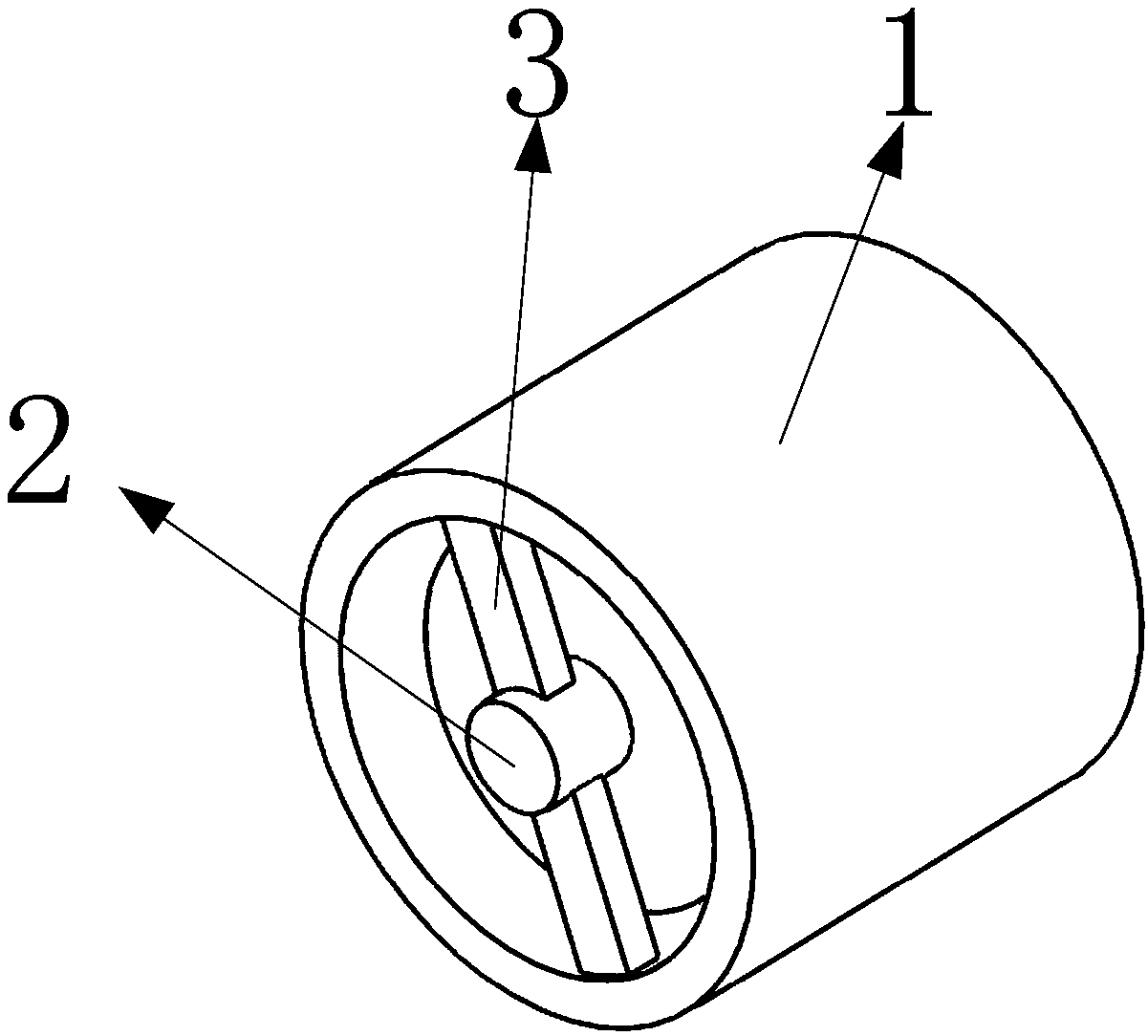
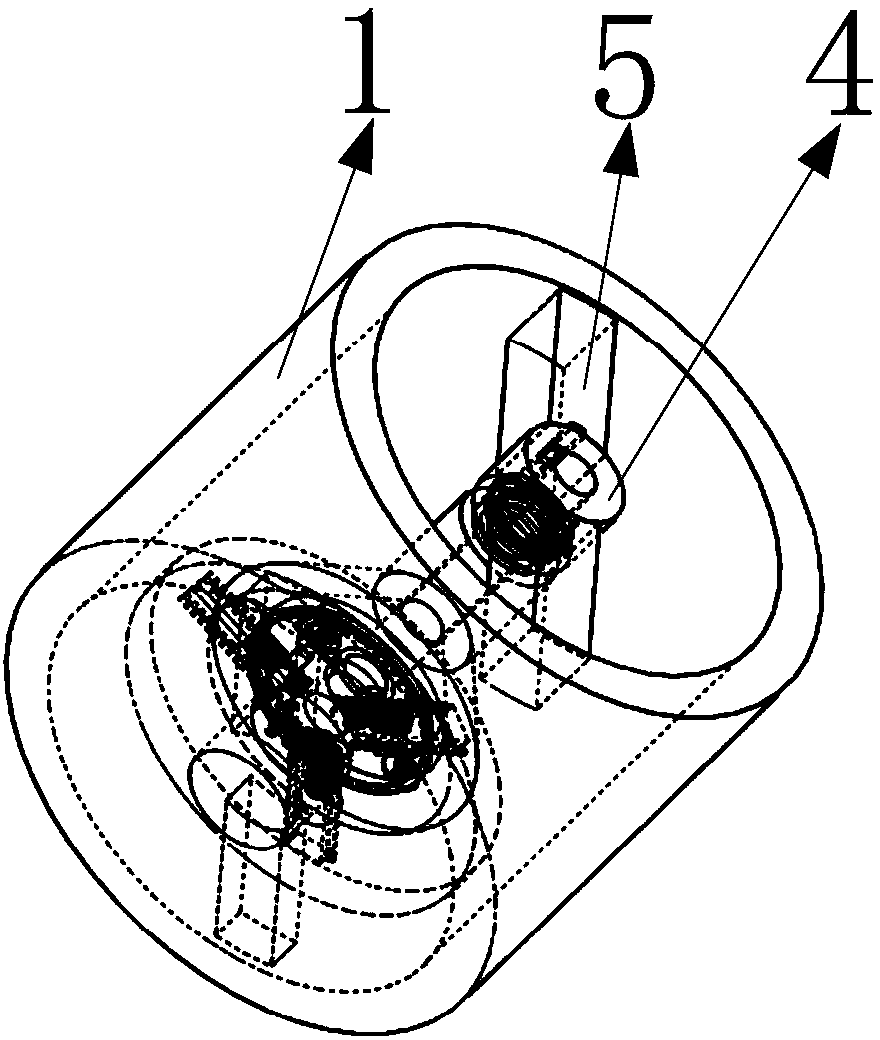
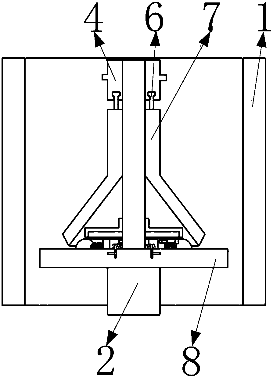
[0032] Such as figure 1 , 2 As shown, it includes a circular fixed shell 1, an input shaft 2, a first fixed column 3, a control rod 4, a second fixed column 5, a T-ring 6, a conical shell 7, a disc 8, a connecting shaft 9, a fixed Disk 10, annular ring gear 11, No. 1 ball 12, No. 2 ball 13, No. 3 ball 14, rectangular groove 15, first gear 16, second gear 17, third gear 18, guide block 19, first fixed spring 20. The second fixed spring 21, fixed block 22, rack 23, fixed shaft 24, such as Figure 5 As shown, one end of the two first fixed columns 3 is fixedly installed on the inner circle surface of one end of the circular fixed shell 1; notches are arranged on the end faces of one end of the two second fixed columns 5; two second fixed columns 5 The end of the column 5 without a notch is fixedly installed on the inner circular surface of the circular fixed shell 1 away from the end of the first fixed column 3; image 3 , 4 As shown, the input shaft 2 is installed between tw...


PUM


Abstract

The invention belongs to the technical field of centrifugal speed adjusters and particularly relates to a centrifugal speed adjuster capable of preventing pulsation. The centrifugal speed adjuster comprises an input shaft, a disc, a conical shell and a control rod. The input shaft rotates to drive the disc to rotate. When the rotating speed of the disc is high, three guiding blocks move to drive three corresponding fixing blocks to move. By means of movement of the three fixing blocks, three corresponding racks can be driven to move. By means of movement of the racks, the corresponding guidingblocks can be driven to move. By means of movement of the guiding blocks, corresponding first fixing springs can be driven to be further compressed. By means of movement of the conical shell, the control rod can be driven to move through T-shaped rings. At the moment, the conical shell can be subjected to the acting force, as combined action of the first fixing springs and centrifugal force, of afirst ball, a second ball and a third ball, and thus the conical shell is subjected to the same pressure; and furthermore, the phenomenon that the centrifugal speed adjuster pulsates is prevented.

Description

technical field [0001] The invention belongs to the technical field of centrifugal governors, in particular to a centrifugal governor for preventing pulsation. Background technique [0002] At present, the existing centrifugal speed governor causes system pressure pulsation during operation, produces vibration and noise, excessive impact and problems affecting the operation process. By designing a centrifugal governor to prevent pulsation and installing a corresponding device, in the process of manufacturing the traditional centrifugal governor, due to the uneven material density of the centrifugal ball, the quality of the centrifugal ball is different. , or the quality is different due to the wear of the centrifugal ball; under the action of different masses of the centrifugal ball, the centrifugal force on the centrifugal ball will be different, so that the centrifugal ball will have different forces on the conical shell. At this time, the centrifugal governor There will ...

Claims


Application Information

Patent Timeline
Patent Type & Authority Applications(China)
IPC IPC(8): F16H57/023F16F15/20
CPCF16H57/023F16F15/20
Inventor 孙茂强
Owner 孙茂强
Why Eureka
Try Eureka