Base of multi-degree of freedom textile machine

A technology of textile machines and degrees of freedom, applied in the direction of supporting machines, mechanical equipment, machine tables/supports, etc., can solve the problems of inconvenient mobile operation, non-universal use, different final requirements of raw materials, etc., and achieve easy adjustment operation and reasonable structural design Effect

Inactive Publication Date: 2018-08-31
SUZHOU BONUQI TEXTILE CO LTD
0 Cites 0 Cited by

AI-Extracted Technical Summary

Problems solved by technology

Even if the same type of equipment, the structure of the machine is similar, but due to the different properties of the raw materials and the final requirements for the fabric, it is generally...

Method used

The structural design of the present invention is reasonable, drives the first mobile base 10 to move by the first driver 11 and the second driver 12, drives the second mobile base 19 by the third driver 17 and the fourth driver 18 to move, by T...

Abstract

The invention discloses a base of a multi-degree of a freedom textile machine. The base comprises a supporting bottom plate, a first baffle, a second baffle, an elastic vibration damping plate body, asupporting seat body, a first transverse sliding track, a second transverse sliding track, a first sliding seat body and a second sliding seat body; a first moving seat body is arranged at the upperend of the first sliding seat body and the upper end of the second sliding seat body; the first sliding seat body is driven by a first driver; the second sliding seat body is driven by a second driver; one side of the upper end of the first moving seat body is provided with a first lateral sliding track; the other side of the upper end of the first moving seat body is provided with a second lateral sliding track; the first lateral sliding track is glidingly provided with a third sliding seat body; the second lateral sliding track is glidingly provided with a fourth sliding seat body; the thirdsliding seat body is driven by a third driver; the fourth sliding seat body is driven by a fourth driver; and a second moving seat body is arranged at the upper end of the third sliding seat body andthe upper end of the fourth sliding seat body.

Application Domain

Stands/trestles

Technology Topic

EngineeringMulti degree of freedom +2

Image

  • Base of multi-degree of freedom textile machine

Examples

  • Experimental program(1)

Example Embodiment

[0013] In order to make the object, technical solution and advantages of the present invention clearer, the present invention will be further described in detail below in conjunction with the accompanying drawings and embodiments. It should be understood that the specific embodiments described here are only used to explain the present invention, not to limit the present invention.
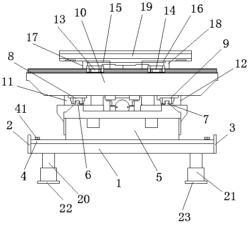
[0014] see figure 1 , figure 1 It is a structural schematic diagram of the present invention.
[0015] The multi-degree-of-freedom textile machine base includes a support base plate 1, a first baffle plate 2 is installed on one side of the support base plate 1, and a second baffle plate is installed on the other side of the support base plate 1 3. An elastic damping plate 4 is installed on the upper end of the supporting base 1, a supporting base 5 is installed on the upper end of the elastic damping plate 4, and a second A transverse sliding track 6, a second transverse sliding track 7 is installed on the other side of the upper end of the support seat body 5, a first sliding seat body 8 is slidably installed on the first transverse sliding track 6, and the The second sliding seat body 9 is slidably installed on the second transverse sliding track 7, and the first mobile seat body 10 is installed on the upper ends of the first sliding seat body 8 and the second sliding seat body 9, and the first sliding seat body The body 8 is driven by the first driver 11, the second sliding seat body 9 is driven by the second driver 12, and the first side sliding track 13 is installed on the upper end side of the first moving seat body 10, The other side of the upper end of the first mobile seat body 10 is equipped with a second lateral sliding track 14, on which a third sliding seat body 15 is slidably installed on the first lateral sliding track 13, on the second side A fourth sliding seat body 16 is slidably installed on the sliding track 14, the third sliding seat body 15 is driven by a third driver 17, and the fourth sliding seat body 16 is driven by a fourth driver 18. The upper ends of the third sliding seat body 15 and the fourth sliding seat body 16 are equipped with a second moving seat body 19 .
[0016] The elastic shock absorbing plate body 4 is installed on the upper end of the support base plate 1 through a plurality of bolts 41, and the first baffle plate 2 and the second baffle plate 3 are used to resist the elastic shock absorbing plate body 4. The bottom end of the base plate 1 is equipped with a first expansion device 20 and a second expansion device 21, a first backing plate 22 is installed at the bottom end of the first expansion device 20, and a first backing plate 22 is installed at the bottom end of the second expansion device 21. There is a second backing plate 23, and both the first backing plate 22 and the second backing plate 23 are elastic backing plates.
[0017] The first driver 11 , the second driver 12 , the third driver 17 and the fourth driver 18 are all single-rod double-acting cylinders.
[0018] The structure design of the present invention is reasonable, the first moving seat body 10 is driven to move by the first driver 11 and the second driver 12, the second moving seat body 19 is driven to move by the third driver 17 and the fourth driver 18, and the second moving seat body 19 is moved by being provided with the second The first telescopic device 20 and the second telescopic device 21 can make the support base plate 1 move up and down, and the present invention can realize multi-degree-of-freedom movement, which is convenient for adjustment operation.
[0019] The above descriptions are only preferred embodiments of the present invention, and are not intended to limit the present invention. Any modifications, equivalent replacements and improvements made within the spirit and principles of the present invention should be included in the protection of the present invention. within range.

PUM

no PUM

Description & Claims & Application Information

We can also present the details of the Description, Claims and Application information to help users get a comprehensive understanding of the technical details of the patent, such as background art, summary of invention, brief description of drawings, description of embodiments, and other original content. On the other hand, users can also determine the specific scope of protection of the technology through the list of claims; as well as understand the changes in the life cycle of the technology with the presentation of the patent timeline. Login to view more.

Similar technology patents

Aggregate screening device for buildings

Owner:SHENZHEN SHENGTENG ENTERPRISE MANAGEMENT CO LTD

Draw-bar box with external article placing groove

PendingCN107212547AReasonable structural design
Owner:ZHEJIANG HONGYI CASES & LEATHER

Energy saver for base station machine room air conditioners

ActiveCN101943453AReasonable structural designSolve the problem of high power consumption
Owner:亿宏技术有限公司

Classification and recommendation of technical efficacy words

  • Reasonable structural design
  • Easy to adjust

Bolt machining all-in-one machine

Owner:ANHUI LIUFANG ZHONGLIAN MECHANICAL SHARE

Internet of things multifunctional intelligent cabinet

PendingCN107622595AReasonable structural designEasy to sell automatically
Owner:王飞天

Automatic operation device of upper drill floor and lower drill floor of drill rod

InactiveCN102230364AReasonable structural designEasy and reliable operation
Owner:SHENGLI OIL FIELD HAISHENG ENVIRONMENTAL PROTECTION ENG

Method for regulating high power laser apparatus light path alignment

InactiveCN101266340Asimple equipmentEasy to adjust
Owner:SHANGHAI INST OF OPTICS & FINE MECHANICS CHINESE ACAD OF SCI

Conductive rubber and application thereof

ActiveCN102176341AGood for dust resistanceEasy to adjust
Owner:DONGGUAN MEMTECH ELECTRONICS MEMTECH ELECTRONICS PRO +2

Preparation method and application of carbon quantum dot/metal organic skeleton catalyst

ActiveCN107754861AImprove photocatalytic reactivityEasy to adjust
Owner:FUJIAN INST OF RES ON THE STRUCTURE OF MATTER CHINESE ACAD OF SCI

LED street lamp

InactiveCN101586758AEasy to adjustSimple structure
Owner:山东魏仕照明科技有限公司
Why Eureka
Try Eureka