
Control device for fuel injection device

A technology for a fuel injection device and a control device, which is applied in the directions of fuel injection device, fuel injection control, special fuel injection device, etc., can solve problems such as deterioration of exhaust performance, and achieve the effect of improving stability and stable injection quantity

Active Publication Date: 2018-08-31
HITACHI ASTEMO LTD
View PDF7 Cites 2 Cited by
  • Summary
  • Abstract
  • Description
  • Claims
  • Application Information

AI Technical Summary

Problems solved by technology

In addition, if there is a part where the fuel and air are uneven, incompletely burned particulate matter will be discharged, and the exhaust performance will deteriorate.

Method used


Image

  • Control device for fuel injection device
  • Control device for fuel injection device
  • Control device for fuel injection device

Examples


Embodiment 1

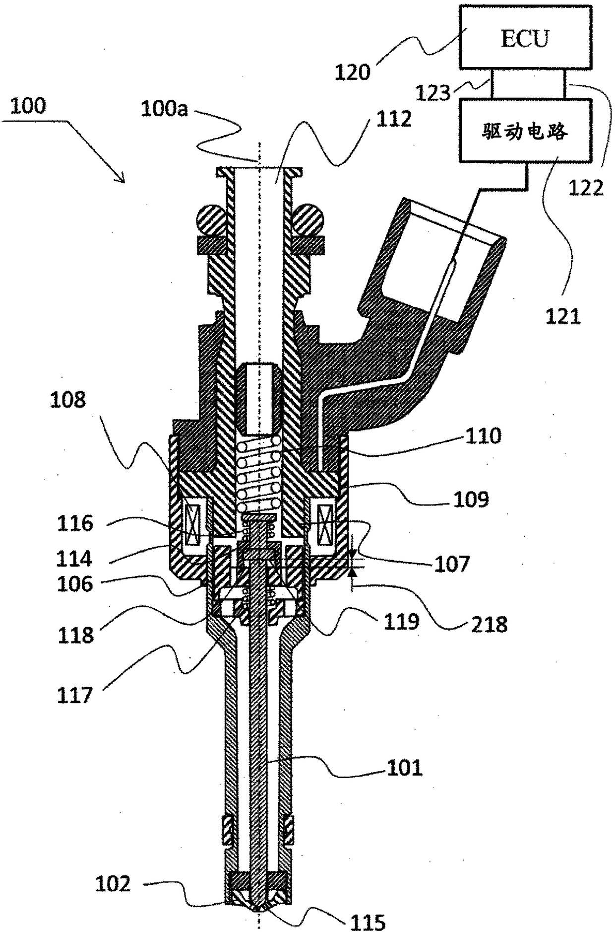
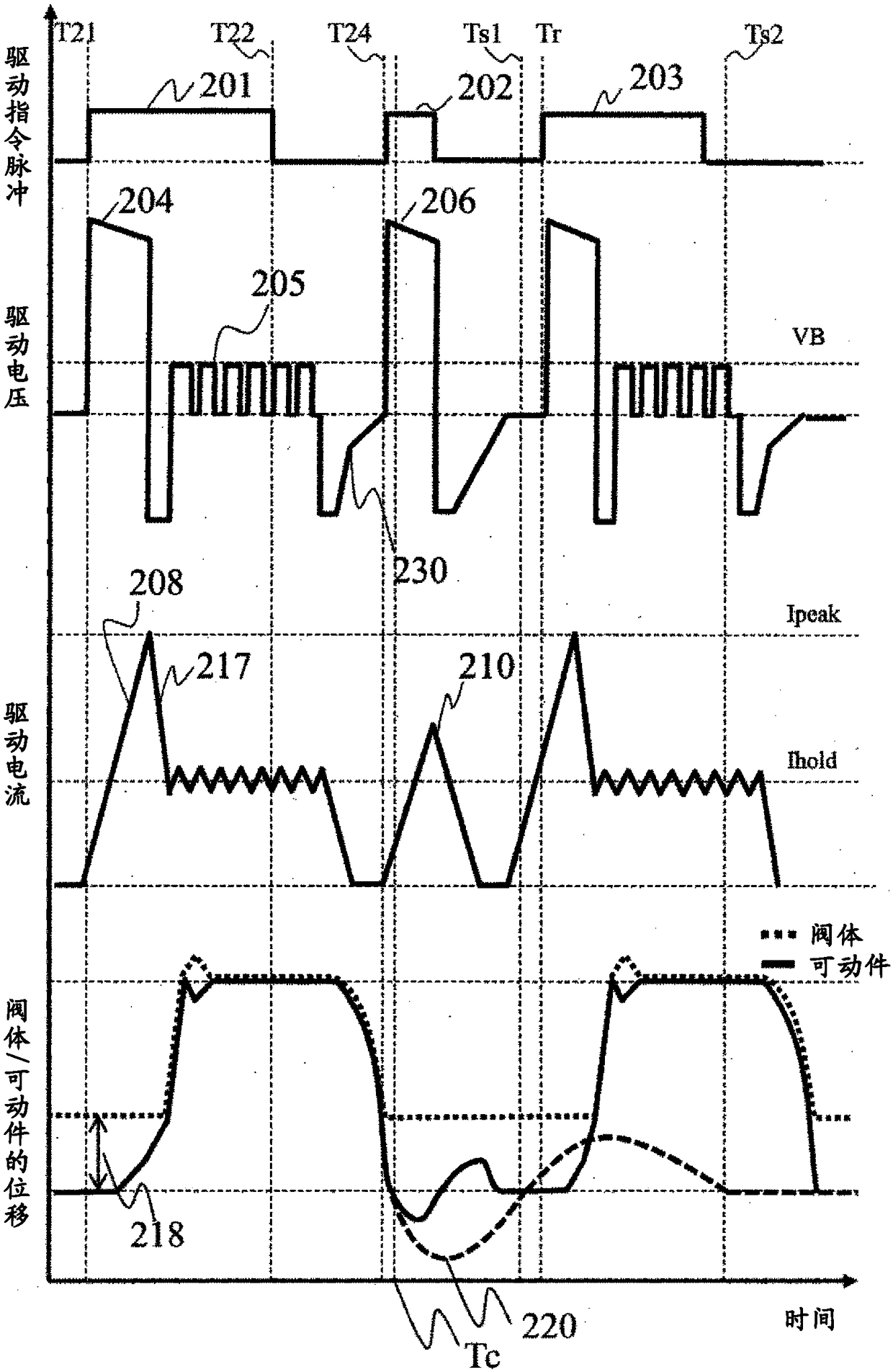
[0024] Hereinafter, Embodiment 1 of the present invention will be described. This embodiment is a control device for controlling a fuel injection device for an internal combustion engine, and involves generating magnetic flux in a magnetic circuit including a movable iron core and a fixed iron core by passing a current through a coil to attract the movable iron core to the side of the fixed iron core. The control device of the electromagnetic fuel injection device that acts on the magnetic attraction force of the iron core to open and close the valve body.

[0025] figure 1 It is a longitudinal cross-sectional view of the fuel injection device 100 in this embodiment and a diagram showing an example of a configuration of a drive circuit 121 for driving the fuel injection device 100 and an ECU (Engine Control Unit) 120 that controls the fuel injection device 100 through the drive circuit 121 . The driving circuit 121 is called "EDU".

[0026] exist figure 1 Here, the longitu...

Embodiment 2

[0060] Below, use Figure 4 ~ Figure 6 The structure and operation of the fuel injection device according to the second embodiment of the present invention will be described.

[0061] Initially, use Figure 4 The structure and basic operation of the fuel injection device of this embodiment will be described. Figure 4 It is a longitudinal cross-sectional view of the fuel injection device 400 of this embodiment and a diagram showing an example of the configuration of a drive circuit 421 and an ECU (Engine Control Unit) 420 for driving the fuel injection device 400 . Furthermore, ECU 420 and drive circuit 421 may be configured as an integral component. At least the driving device of the fuel injection device (electromagnetic fuel injection valve) is a device that generates the driving voltage of the fuel injection device, which may be a device in which the ECU and the driving circuit are integrated, or a single driving circuit.

[0062] The ECU 420 reads signals indicating th...


PUM


Abstract

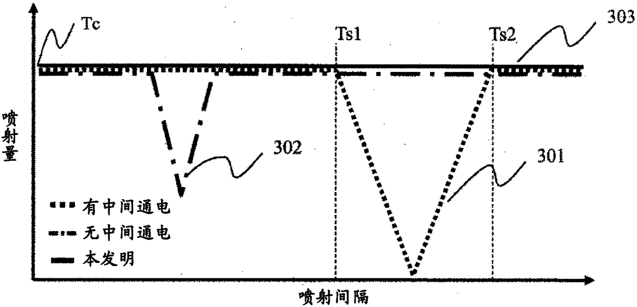
The present invention provides a control device for a fuel injection device, said control device improving the operational stability of a valve during valve opening and stabilizing the injection amount even when the interval between an earlier fuel injection (first fuel injection) and a subsequent fuel injection (second fuel injection) has changed. Provided is a control device for a fuel injectiondevice that is provided with a valve, which opens a fuel passage by moving away from a valve seat, a movable iron core, which implements a valve opening / closing operation, and a fixed iron core, which draws the movable iron core thereto due to the flow of a current through a coil, wherein the control device is provided with a control unit that, when energization of the coil is cut off and the movable iron core moves in the direction of separation from a fixed iron core after the coil has been energized to draw the movable iron core to the fixed core, performs intermediate energization to re-energize the coil, said control unit controlling whether or not to perform the intermediate energization in accordance with the injection interval of the fuel injection device.

Description

technical field [0001] The invention relates to a control device for a fuel injection system. Background technique [0002] In recent years, for the purpose of reducing fuel consumption of internal combustion engines, miniaturized engines that obtain output through a supercharger while reducing displacement have appeared. In a downsized engine, by reducing the displacement, the impact loss can be reduced and the fuel consumption can be reduced. [0003] In a small engine, since the bore diameter in the engine barrel tends to be reduced, injected fuel adheres to the cylinder wall surface, which may degrade the exhaust performance. In addition, if a part where the fuel and air are not uniform is generated, incompletely burned particulate matter is discharged, and the exhaust performance deteriorates. [0004] Due to the homogenization of the air and fuel in the engine barrel and the fuel adhering to the wall surface in the barrel, there is a split injection that divides the ...

Claims


Application Information

Patent Timeline
Patent Type & Authority Applications(China)
IPC IPC(8): F02D41/32F02D41/04F02D41/20F02M51/06F02M61/16
CPCF02D41/402F02D2041/2037F02D2041/2044F02M51/0685F02M2200/50F02D41/20Y02T10/40F02D41/3005F02D2041/2051
Inventor 宫本明靖丰原正裕向原修安川义人
Owner HITACHI ASTEMO LTD
Learn More