Method for system layout optimization of retroreflection based display systems

A display system and retroreflection technology, applied in stereoscopic systems, instruments, projection devices, etc., can solve problems such as non-linear increase in cost, difficulty in obtaining screen size, and reduction in screen brightness

Active Publication Date: 2021-04-02
MIRRAVIZ
View PDF10 Cites 0 Cited by
  • Summary
  • Abstract
  • Description
  • Claims
  • Application Information

AI Technical Summary

Problems solved by technology

In general, screen sizes significantly larger than 80 inches in diagonal size are difficult to achieve due to various considerations
For flat-panel displays, the non-linear increase in cost as screen size increases and high power consumption can limit screen sizes to less than 80 inches at typical consumer price points
For projection-based displays, reduced screen brightness and increased power consumption, projector size, and projector noise can be significant limitations if the display size increases beyond 80 inches
Another limitation of current state-of-the-art displays is that no low-cost solution exists to enable multiple viewers to view personalized content simultaneously on the same screen area
Furthermore, no simple solution for naked-eye three-dimensional (3D) immersive viewing currently exists for both types of displays

Method used


Image

  • Method for system layout optimization of retroreflection based display systems
  • Method for system layout optimization of retroreflection based display systems
  • Method for system layout optimization of retroreflection based display systems

Examples


Embodiment Construction

[0034] While various embodiments of the invention have been shown and described herein, it would be obvious to those skilled in the art that such embodiments are provided by way of example only. Numerous variations, changes, and substitutions will occur to those skilled in the art without departing from the invention. It should be understood that various alternatives to the embodiments of the invention described herein may be employed.

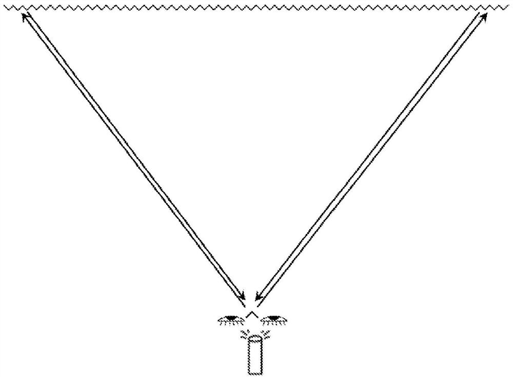
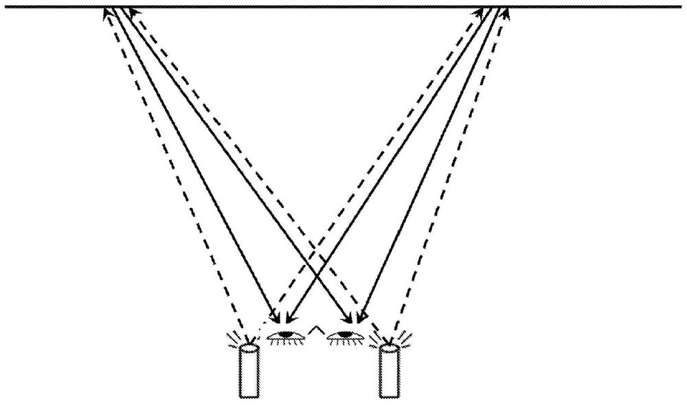
[0035] As used herein, the term "retroreflective" (also referred to herein as "retroreflective" or "retroreflective" or simply "RR") generally refers to a device or device that reflects light back to its source with minimal light scattering. surface. In a retroreflective screen, electromagnetic waves are reflected back along a vector parallel to but opposite to the direction of the wave source. Retroreflective screens comprise a retroreflective surface composed of many small individual corner cube reflective elements or other RR elements suc...


PUM


Abstract

The present disclosure provides a display system that may include a retroreflective screen configured to reflect incident light in a direction opposite to the direction of propagation of the incident light, and may include a The light is projected onto the retro-reflective screen by the projector. An array of optical elements or a single optical element may be located between the retroreflective screen and the projector. The array of optical elements or the individual optical elements are capable of directing the light from the projector to the retroreflective screen in such a manner that the picture or video is viewable by a user at an viewing angle of at least about 2 degrees .

Description

[0001] cross reference [0002] This application claims priority to US Provisional Patent Application Serial No. 62 / 255,218, entitled "Methods for System Layout Optimization for Retro-Reflective Based Display Systems," filed November 13, 2015, which is incorporated herein by reference in its entirety. Background technique [0003] Current state-of-the-art display systems generally include flat panel displays or projector-based displays. Flat panel displays are generally based on liquid crystal display (LCD) pixels with light emitting diode (LED) backlights or plasma based screens. In general, screen sizes significantly larger than 80 inches in diagonal size are difficult to obtain due to various considerations. For flat panel displays, the non-linear increase in cost as screen size increases and high power consumption can limit screen sizes to below 80 inches at typical consumer price points. For projection-based displays, reduced screen brightness and increased power consu...

Claims


Application Information

Patent Timeline
Patent Type & Authority Patents(China)
IPC IPC(8): H04N13/363G02B30/35G03B21/28G03B21/60G03B33/10H04N13/39
CPCG03B21/28G03B21/60G03B33/10H04N13/363G02B30/36G02B30/35H04N13/39G02B27/14
Inventor 迈克尔·W·王
Owner MIRRAVIZ
Why Eureka
Try Eureka