Chemical fertilizer applicator
A fertilizer applicator and fertilizer technology, applied in agricultural machinery and implements, shovels, plows, etc., can solve the problems of easy cake formation, high cost, waste, etc., and achieve the effect of non-retention of flow rate, convenient operation and uniform flow rate
- Summary
- Abstract
- Description
- Claims
- Application Information
AI Technical Summary
Problems solved by technology
Method used
Image
Examples
Embodiment Construction
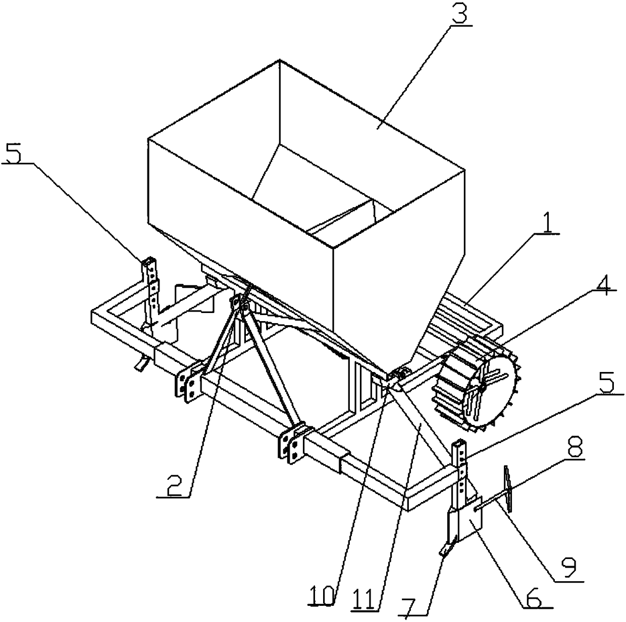
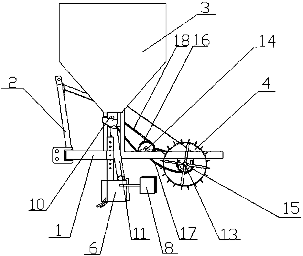
[0017] Such as Figure 1-Figure 2 As shown, a fertilizer applicator includes a frame 1, a traction frame 2, a rolling wheel, a fertilizer box 3, a driving shaft 13, a bearing seat, a transmission shaft 14, a dial shaft, a dial wheel, a first driving sprocket 15, The first driven sprocket, the second driving sprocket 16, the second driven sprocket, the first chain 17, the second chain 18, the chute, the feeding pipe, the furrowing plow and the buried soil plate.
[0018] The traction frame 2 is fixedly mounted on the front end of the frame 1, the fertilizer box 3 is fixedly arranged on the frame 1 behind the traction frame 2, and the bearing seats are arranged symmetrically on the left and right sides of the frame behind the fertilizer box 3 1, the transmission shaft 14 is assembled on the bearing seat on the frame 1 behind the fertilizer box 3, the driving shaft 13 is fixedly arranged on the frame 1 behind the transmission shaft 14, and the rolling wheel is assembled At the t...
PUM
 Abstract
Description
Claims
Application Information
 - R&D
- Intellectual Property
- Life Sciences
- Materials
- Tech Scout
- Unparalleled Data Quality
- Higher Quality Content
- 60% Fewer Hallucinations
Browse by: Latest US Patents, China's latest patents, Technical Efficacy Thesaurus, Application Domain, Technology Topic, Popular Technical Reports.
© 2025 PatSnap. All rights reserved.Legal|Privacy policy|Modern Slavery Act Transparency Statement|Sitemap|About US| Contact US: help@patsnap.com


