
Mechanical washing device for electronic components

A technology for mechanical cleaning and electronic components, applied to cleaning methods and appliances, cleaning methods using liquids, cleaning methods using tools, etc., can solve the problems of wasting time, dust attached, low cost, etc., and the method is simple, fast, and improved The effect of work efficiency and simple structure

Inactive Publication Date: 2018-09-04
ANHUI JINAIER ELECTRICAL APPLIANCE TECH
View PDF7 Cites 1 Cited by
  • Summary
  • Abstract
  • Description
  • Claims
  • Application Information

AI Technical Summary

Problems solved by technology

Among them, the cost of the manual cleaning method is relatively low. The cleaning personnel use tweezers to pick up the cotton ball with the organic solution to clean the place with pollutants on the surface of the silicon wafer, so as to achieve the cleaning effect, but this cleaning method is more expensive. Increases the possibility of scratches on the surface of silicon wafers, which will affect the quality of electronic components
The mechanical cleaning method uses machinery such as high-pressure chip wipers and mechanical brushing machines, which can effectively clean the pollutants on electronic components. Compared with manual cleaning methods, mechanical cleaning methods are less likely to cause damage to electronic components. Small, general-purpose mechanical brushing machines cannot automatically clean the front and back sides of electronic components at the same time. When the other side of the electronic component needs to be cleaned, the electronic component needs to be removed and placed again. This process may cause dust to reattach to the surface of the electronic component, and This operation process is time consuming

Method used


Image

  • Mechanical washing device for electronic components
  • Mechanical washing device for electronic components
  • Mechanical washing device for electronic components

Examples


Embodiment Construction

[0022] The technical solutions in the embodiments of the present invention will be clearly and completely described below. Obviously, the described embodiments are only some of the embodiments of the present invention, but not all of them. Based on the embodiments of the present invention, all other embodiments obtained by persons of ordinary skill in the art without making creative efforts belong to the protection scope of the present invention.

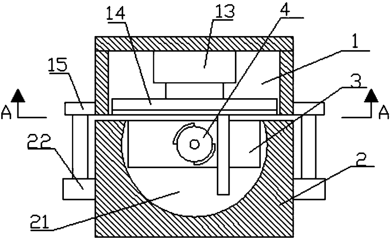
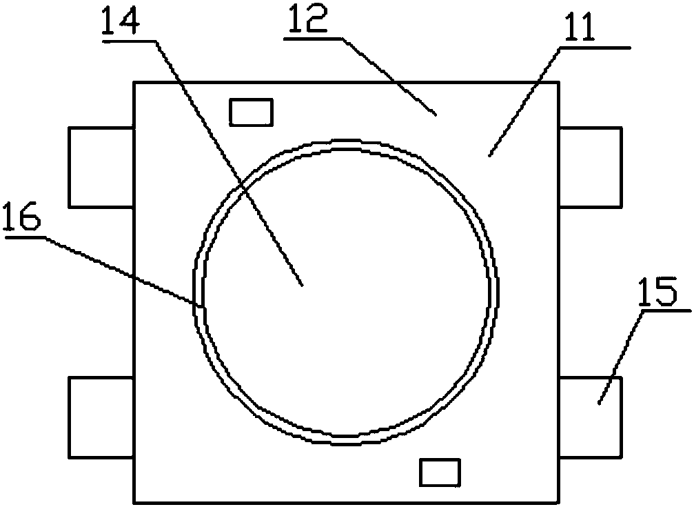
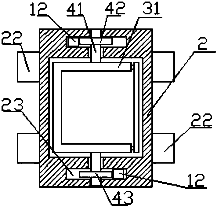
[0023] Such as Figure 1 to Figure 5 As shown, a mechanical cleaning device for electronic components includes a carrying device 2 and a cleaning device 1. The cleaning device 1 includes a housing 11, and the outer surface of the lower end of the housing 11 is symmetrically provided with support plates 15 on the left and right sides. The housing 11 A cleaning assembly is provided in the middle, and the carrying device 2 includes a carrying base, and a clamping assembly 3 is arranged in the carrying base.

[0024] In this embodiment...


PUM


Abstract

The invention discloses a mechanical washing device for electronic components and relates to the technical field of micro-electronics washing equipment. The mechanical washing device comprises a bearing device and a washing device body. The washing device body comprises a shell. The left side and the right side of the outer surface of the lower end of the shell are symmetrically provided with supporting plates. The middle of the shell is provided with a washing assembly. The bearing device comprises a bearing base. The bearing base is internally provided with a clamping assembly. The middle ofthe shell is provided with a cylindrical groove. The bottom of the cylindrical groove is provided with a power device. The power device comprises a motor. The motor is arranged on the bottom of the cylindrical groove. The extending end of the motor is provided with a round wiping piece, and the lower surface of the wiping piece is provided with a wiping brush. The mechanical washing device can rapidly wash away particles, dust or residual gum on the upper surfaces and the lower surfaces of the electronic components. By means of opening and closing of the mechanical washing device, overturningof the electronic components is automatically completed, the method is simple and rapid, and the working efficiency is greatly improved.

Description

technical field [0001] The invention relates to the technical field of microelectronic cleaning equipment, in particular to a mechanical cleaning device for electronic components. Background technique [0002] During the production and processing of microelectronic products, the products will be contaminated due to the influence of various factors. Generally, these pollutants will remain on the surface of the product through physical adsorption or chemical adsorption, which will have a serious impact on the quality and service life of the product. For example, when silicon wafers are produced, ions or particles of some pollutants will remain on the surface of silicon wafers or in the oxide film. This is mainly because during the production and processing process, the chemical bonds of silicon wafers are destroyed, which intensifies the adsorption of pollutants. This situation brings great difficulty to the cleaning work of silicon wafer. At present, there are mainly two t...

Claims


Application Information

Patent Timeline
IPC IPC(8): B08B1/04B08B3/08B08B13/00
CPCB08B3/08B08B13/00B08B1/143B08B1/32
Inventor 艾蒙雁
Owner ANHUI JINAIER ELECTRICAL APPLIANCE TECH
Learn More