
Explosion-proof valve for engine

An explosion-proof valve and engine technology, applied to engine components, machines/engines, valve devices, etc., can solve the problems of insufficient gas discharge, valve core wear, etc., to shorten the time and increase the reaction efficiency.

Active Publication Date: 2019-12-13
玉环鑫进机械有限公司
View PDF5 Cites 1 Cited by
  • Summary
  • Abstract
  • Description
  • Claims
  • Application Information

AI Technical Summary

Problems solved by technology

[0004] This technical solution can realize the discharge of combustible gas in the intake pipe from the exhaust hole provided on the casing when the flashback phenomenon occurs, effectively protecting the intake pipe, air filter and intercooler of the engine; but In this scheme, when the explosion-proof valve is exhausted, the valve core is subjected to bending moment, which leads to serious wear of the valve core; the gas in the intake pipe is not exhausted enough

Method used


Image

  • Explosion-proof valve for engine
  • Explosion-proof valve for engine
  • Explosion-proof valve for engine

Examples


Embodiment approach

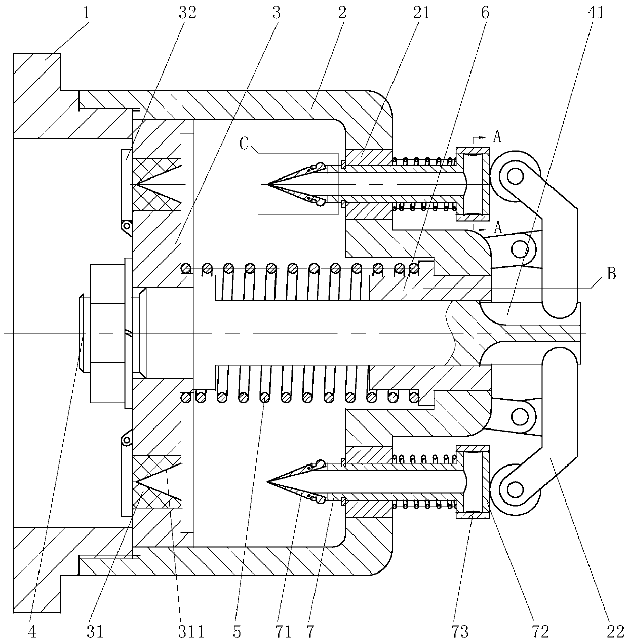
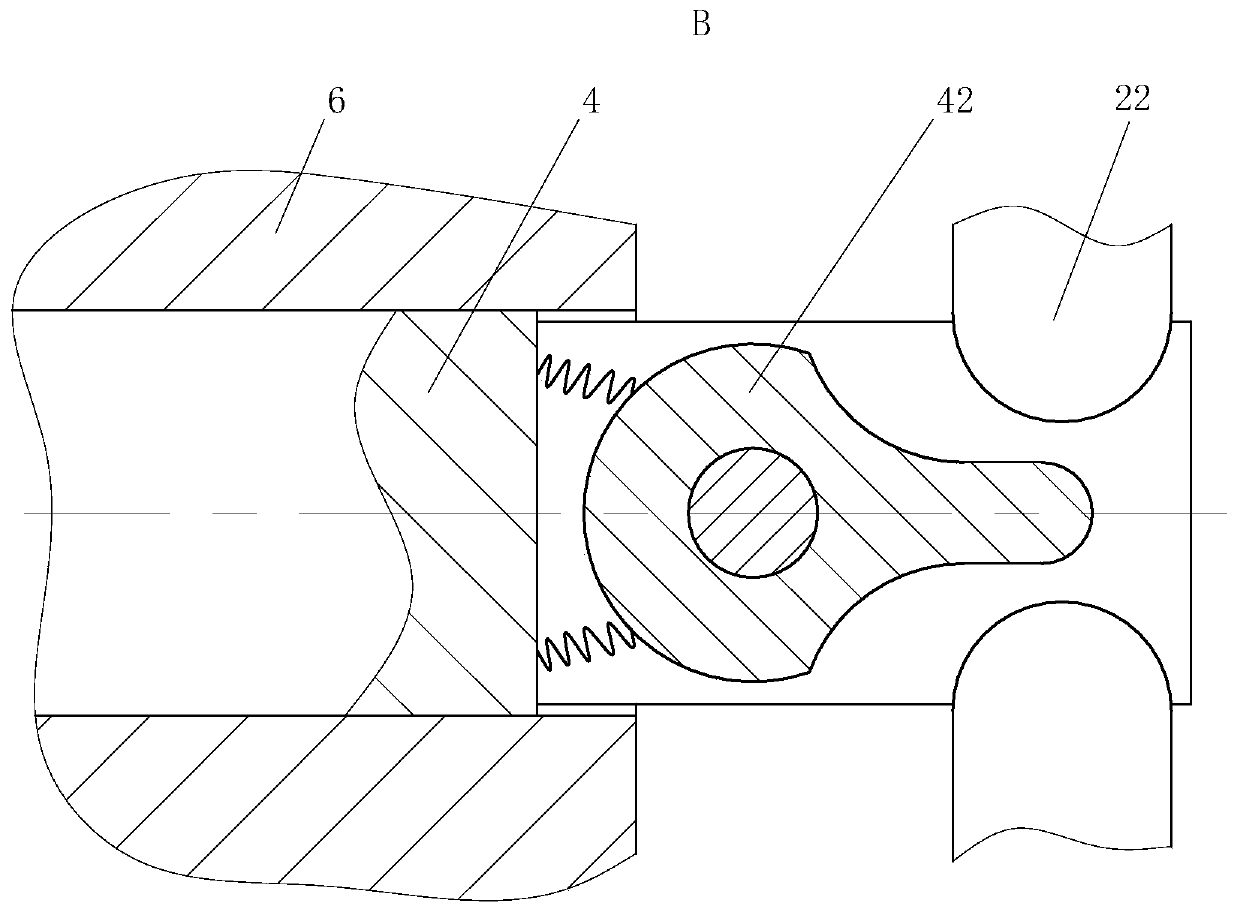
[0025] As an embodiment of the present invention, the chute 41 is a rectangular slot, and a swing block 42 is installed in the chute 41 through a rotating shaft; Two sets of springs are arranged symmetrically between the arc surface and the chute 41, and the swing block 42 is driven by the main shaft 4 to move, so that the arc surface of the swing block 42 squeezes the swing rod 22; when working, the high-pressure gas pushes the valve core 3 to move, and the valve core 3 Drive the main shaft 4 to move, the main shaft 4 drives the swing block 42 to move, the two arc surfaces at one end of the swing block 42 squeeze the other end of the swing rod 22, when the pressure of the swing rod 22 on the two arc surfaces is different, the swing Block 42 automatically adjusts the swing angle around the rotating shaft to ensure that the eccentric moment on the two arc surfaces will not act on the main shaft 4 .

[0026] As an embodiment of the present invention, a dust shield 73 is provided...


PUM


Abstract

The invention belongs to the technical field of valves and particularly discloses an anti-explosion valve for an engine. The anti-explosion valve comprises a conical sleeve, an exhaust pipe, swing pieces, a sliding bearing, a spring and a clamp spring. The conical sleeve is fixedly connected in a cylindrical hole in the end face of a valve core. The center of the conical sleeve is provided with acircular cone groove. The exhaust pipe is slidably installed in a center hole of the sliding bearing. One end of the exhaust pipe is provided with a set of swing pieces. The middles of the swing pieces are hinged to one end of the exhaust pipe. A torsion spring is arranged at the hinged joint. Arc-shaped protrusions are arranged at one ends of the swing pieces. The set of swing pieces form a circular cone shape in a surrounding mode. According to the anti-explosion valve, the swing pieces at the end of the exhaust pipe penetrate through the conical sleeve, the face of the circular cone groovein the conical sleeve extrudes the arc-shaped protrusions on the swing pieces. The swing pieces swing. The circular cone groove of the conical sleeve deforms and expands to be open, then high-pressuregas is discharged through the exhaust pipe, and finally the valve is opened while the anti-explosion valve resists fiercely exploding pressure.

Description

technical field [0001] The invention belongs to the technical field of valves, in particular to an explosion-proof valve for an engine. Background technique [0002] At present, commonly used engines, especially pneumatic engines, use premixed intake air during use, so the intake pipe is filled with flammable gas. If backfire occurs, the combustible gas in the intake pipe will burn violently and cause The pressure rises sharply, resulting in damage to the intake pipe, even the air filter and intercooler, or even more serious accidents. [0003] In the prior art, some technical solutions of explosion-proof valves for engines have also appeared. For example, a Chinese patent with application number 201310019357.X discloses a kind of explosion-proof valve for engines, which includes a base. The end far away from the base is provided with an exhaust hole, the housing is provided with a main shaft, the end of the main shaft close to the base is provided with a valve core, and th...

Claims


Application Information

Patent Timeline
Patent Type & Authority Patents(China)
IPC IPC(8): F02B77/08F16K17/04
CPCF02B77/082F16K17/0413F16K17/0426
Inventor 邢箫
Owner 玉环鑫进机械有限公司
Learn More