
Micro analog power transmission line comprehensive experiment cabinet for power system

A transmission line and power system technology, applied in the direction of measuring electricity, measuring electrical variables, instruments, etc., can solve the problems of messy experimental platform, inconsistent interface, high experimental voltage level, etc., to improve experimental safety, reduce complexity, and improve safety effect

Active Publication Date: 2018-09-04
SHANDONG UNIV
View PDF8 Cites 4 Cited by
  • Summary
  • Abstract
  • Description
  • Claims
  • Application Information

AI Technical Summary

Problems solved by technology

In the traditional physical simulation method, there are certain problems in the transmission line simulation: the simulated transmission line unit and the simulated line unit are erected separately, and the external connection is complicated, which leads to the messy experimental platform; the high voltage level of the experiment reduces the safety and feasibility of the experiment; the simulation The unit is bulky, the interface is not uniform, and it is very difficult to change the topology of the transmission line network; the monitoring and control unit includes voltage transformers, current transformers, power meters, power factor meters, circuit breakers, etc. and the difficulty of coordinated control
The above reasons make it difficult for traditional analog transmission lines to meet the simulation requirements of modern power system transmission lines.

Method used


Image

  • Micro analog power transmission line comprehensive experiment cabinet for power system
  • Micro analog power transmission line comprehensive experiment cabinet for power system
  • Micro analog power transmission line comprehensive experiment cabinet for power system

Examples


Embodiment Construction

[0040] The present invention will be further described below in conjunction with the accompanying drawings and embodiments.

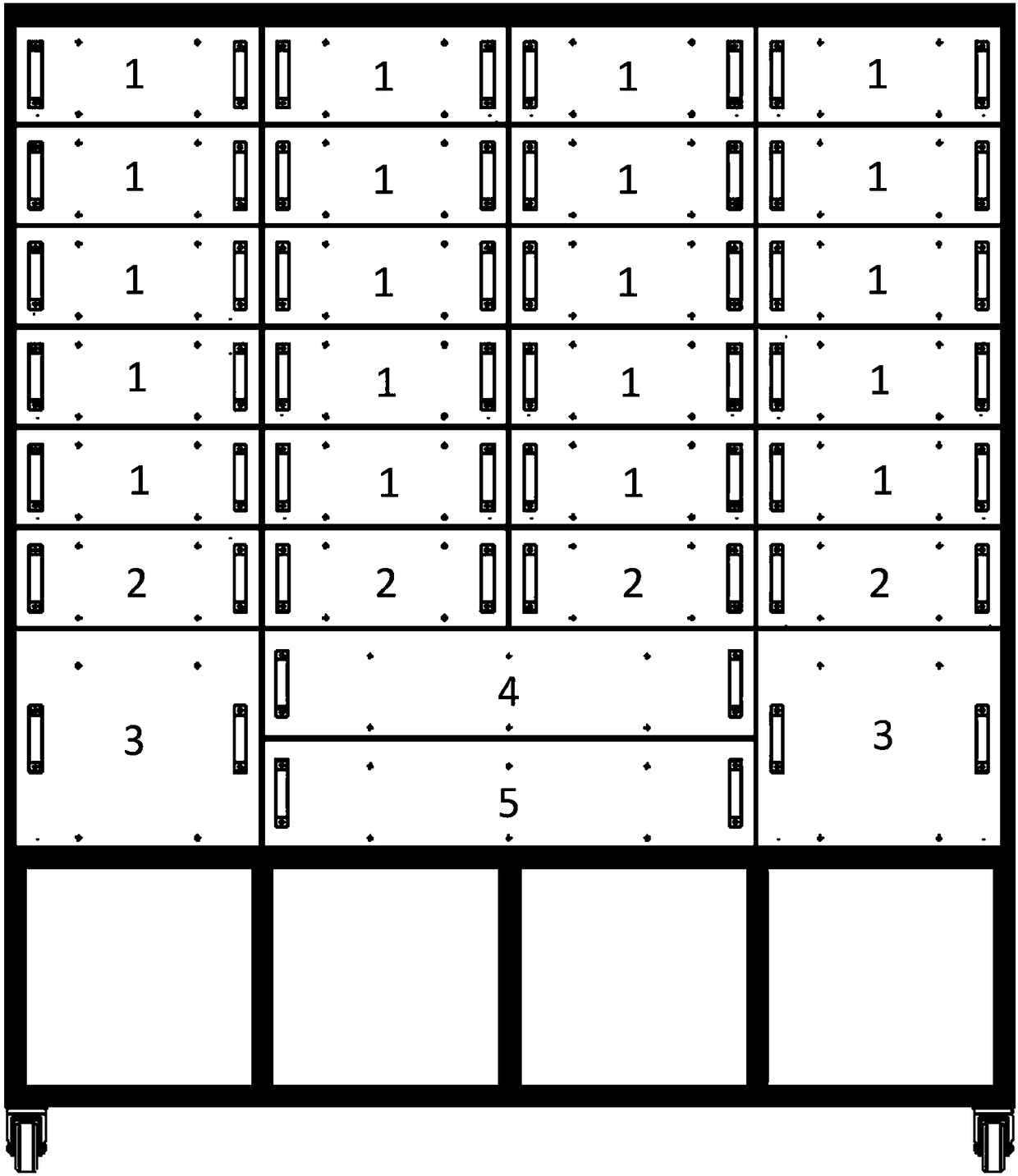
[0041] A comprehensive experimental cabinet for power system miniature analog transmission lines, such as figure 1 As shown, including the comprehensive experiment cabinet, the bottom of the comprehensive experiment cabinet is provided with four universal wheels with locks, and the comprehensive experiment cabinet is provided with a plurality of miniature standardized analog transmission line unit slots, a plurality of miniature standardized analog busbar unit slots, and a plurality of Lightweight synchrophasor measurement unit slot, at least one network switch slot and at least one junction box 5;

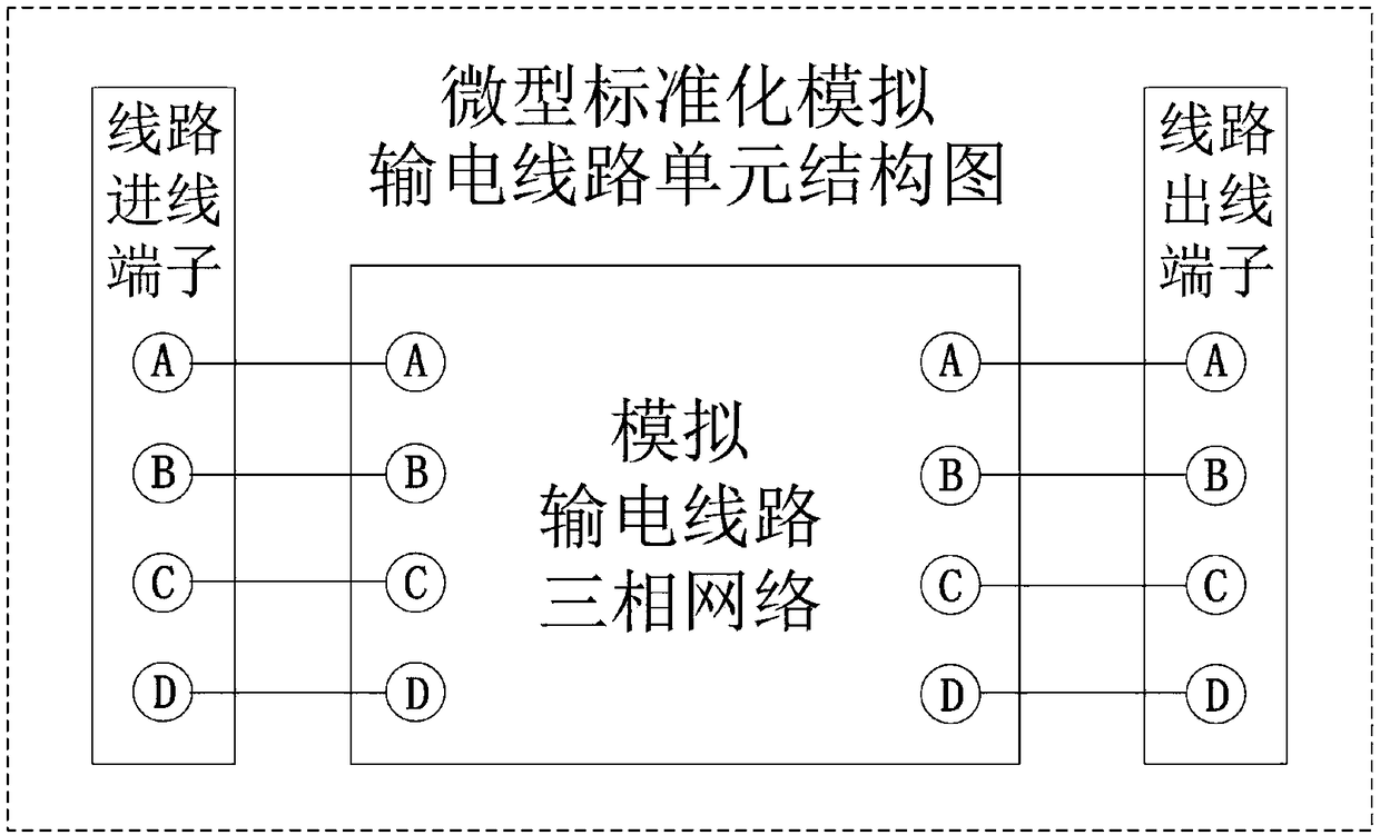
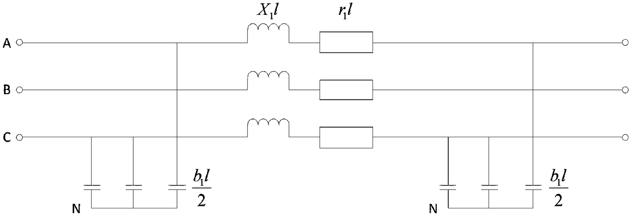
[0042] Each of the miniature standardized analog transmission line unit slots is provided with a miniature standardized analog transmission line unit 1, and the miniature standardized analog bus unit slot is provided with a miniature standardized analog bus...


PUM


Abstract

The invention discloses a micro analog power transmission line comprehensive experiment cabinet for a power system. The micro analog power transmission line comprehensive experiment cabinet for a power system includes a comprehensive experiment cabinet, wherein the comprehensive experiment cabinet is provided with a plurality of micro standardized analog power transmission line unit slots, a plurality of micro standardized analog bus unit slots, a plurality of light synchronous phasor measurement unit slots, at least one network switch slot and at least one junction box; and each of the microstandardized analog power transmission line unit slots is provided with a micro standardized analog power transmission line unit, and each of the micro standardized analog bus unit slots is provided with a micro standardized analog bus unit, and the micro standardized analog bus unit is provided with a micro standardized analog bus unit; each light synchronous phasor measurement unit slot is provided with a light synchronous phasor measurement unit, and the network switch slot is provided with a network switch. The micro analog power transmission line comprehensive experiment cabinet for a power system has the advantages of high simulation precision, easy structure adjustment, high integration level, high response speed, high timeliness, stable network transmission, and seamless integration with server applications.

Description

technical field [0001] The invention relates to the technical field of miniature dynamic simulation of electric power system, in particular to a comprehensive experimental cabinet for miniature simulation of power system transmission lines. Background technique [0002] The simulation methods of power system transmission lines are divided into physical simulation methods and software simulation methods. [0003] The physical simulation method is based on the law of similarity, and the simulated components and the prototype transmission line have the same physical characteristics and mathematical parameters (per unit value). This method is to shrink the actual transmission line according to a certain ratio. The simulation process does not require the similarity of the electromagnetic field in space, nor does it require the propagation speed of the wave process to be similar along the line. It only requires that the voltage and current at certain points on the line change with...

Claims


Application Information

Patent Timeline
Patent Type & Authority Applications(China)
IPC IPC(8): G01R31/00
CPCG01R31/00
Inventor 张恒旭李昊
Owner SHANDONG UNIV
Learn More