
Multi-target reactive power optimization method based on chaotic particle swarm algorithm

A chaotic particle swarm and optimization method technology, applied in reactive power compensation, reactive power adjustment/elimination/compensation, etc., can solve the problem that the weight coefficient cannot be adjusted adaptively, the multimodal function cannot be searched, and the global search capability is limited. and other problems, to avoid premature convergence, improve voltage quality, and improve global search capabilities.

Inactive Publication Date: 2018-09-04
CENT SOUTH UNIV
View PDF0 Cites 12 Cited by
  • Summary
  • Abstract
  • Description
  • Claims
  • Application Information

AI Technical Summary

Problems solved by technology

[0004] Particle Swarm Optimization algorithm PSO (ParticleSwarmOptimization) is an iterative multi-point random search intelligent optimization algorithm, which has the characteristics of simple operation and less required setting parameters, and has been applied to reactive power optimization by electric power workers. The particle swarm reactive power optimization algorithm is iterated through randomly generated initial particles, which may have blind spots for multimodal functions that cannot be searched, and are easy to fall into local solutions; in addition, the weight coefficients cannot be adaptively adjusted during iterations , limiting the global search capability

Method used


Image

  • Multi-target reactive power optimization method based on chaotic particle swarm algorithm
  • Multi-target reactive power optimization method based on chaotic particle swarm algorithm
  • Multi-target reactive power optimization method based on chaotic particle swarm algorithm

Examples


Embodiment Construction

[0014] The present invention will be further described in detail below in conjunction with the accompanying drawings and examples. The following examples are explanations of the present invention and the present invention is not limited to the following examples.

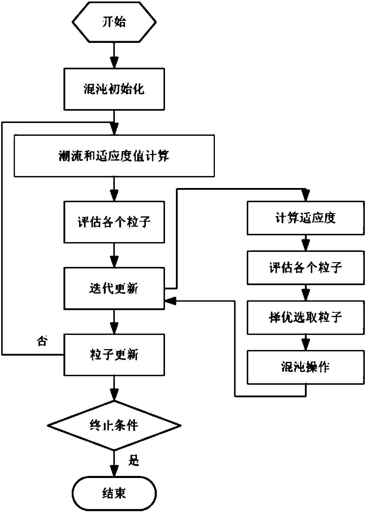
[0015] see figure 1 , the present embodiment is a multi-objective reactive power optimization method based on chaotic particle swarm optimization, which is characterized in that the method includes:

[0016] Input the original data of the particle swarm to the adaptive chaotic particle swarm algorithm program, randomly generate an n-dimensional chaotic vector through the chaotic algorithm, and then calculate N chaotic variables through the Logistic complete chaotic iterative formula;

[0017] (1) Input the original data of the particle swarm to the adaptive chaotic particle swarm algorithm program, randomly generate an n-dimensional chaotic vector through the chaotic algorithm, and then calculate N chaotic variables...


PUM


Abstract

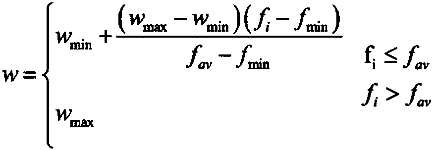
The invention provides a multi-target reactive power optimization method based on a chaotic particle swarm algorithm, and relates to a multi-target reactive power optimization method. The multi-targetreactive power optimization method aims to solve the problem that the multi-objective reactive power optimization control variable may fall into a local optimal solution and the speed of solving theoptimal value is low. The multi-target reactive power optimization method includes the steps: 1) inputting raw data of the particle swarm to an adaptive chaotic particle swarm algorithm program; 2) according to the magnitude of the fitness values, preferentially selecting the first m particles as the initial position of the particle swarm; 3) obtaining the inertia weight w of each particle by calculating the inertia weight coefficient formula, and preferentially selecting the first M optimal particles to perform chaotic optimization calculation; 4) according to the particle swarm reactive power optimization algorithm, updating the velocity and the position of the particles, that is, the iterative correction and the value of the control variable; and 5) determining whether the iterative termination condition is satisfied, that is, completing the multi-target reactive power optimization method based on the chaotic particle swarm optimization algorithm. The multi-target reactive power optimization method based on a chaotic particle swarm algorithm is applied to the electric power system field.

Description

technical field [0001] The invention relates to a multi-objective reactive power optimization method based on a chaotic particle swarm algorithm. Background technique [0002] Power system reactive power optimization is to study when the system structure parameters and load conditions have been given, through the optimization calculation of some control variables in the system, to find the system's power consumption under the premise of satisfying all specific constraints. An operation control scheme when one or more performance indicators are optimal. [0003] At present, there are many methods for solving reactive power optimization. The traditional mathematical programming methods mainly include nonlinear programming and linear programming. The difficulty of the conventional method is mainly the rounding problem of discrete variables, which is easy to fall into local optimum and produce the "curse of dimensionality" problem. In recent years, in order to make up for the ...

Claims


Application Information

Patent Timeline
IPC IPC(8): H02J3/18
CPCY02E40/30H02J3/18
Inventor 凌玉华刘峰
Owner CENT SOUTH UNIV
Learn More