Camera configuration method and device

A configuration method and camera technology, applied in the field of computer vision, can solve the problem of not considering other factors, and achieve the effect of ensuring the effect of motion capture, the configuration is economical and the configuration cost is reasonable.

Active Publication Date: 2018-09-04
SHENZHEN REALIS MULTIMEDIA TECH CO LTD
View PDF13 Cites 2 Cited by
  • Summary
  • Abstract
  • Description
  • Claims
  • Application Information

AI Technical Summary

Problems solved by technology

[0004] However, in the prior art, when determining the camera configuration method, other factors affecting the camera configuration method are not considered. It can be seen that there is still room for improvement and optimization when determining the camera configuration method

Method used


Image

  • Camera configuration method and device
  • Camera configuration method and device
  • Camera configuration method and device

Examples


Embodiment 1

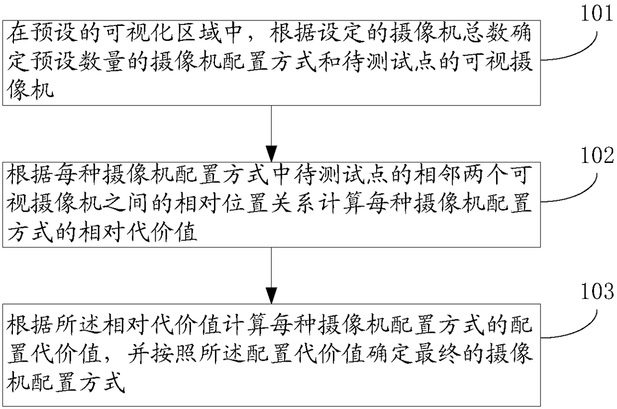
[0031] figure 1 It is a flowchart of a camera configuration method provided in Embodiment 1 of the present invention. The execution subject of this embodiment may be a computer device or a functional unit in the computer device. This embodiment specifically includes steps S101 to S103, which are described in detail as follows:

[0032] S101: In the preset visualization area, determine a preset number of camera configuration modes and visible cameras of the points to be tested according to the set total number of cameras.

[0033] The preset visualization area can be any size created by the user in the optical motion capture system, and contains the simulated area of ​​obstacles such as columns and walls. In the preset visualization area, users can further set camera parameters, including setting the total number of cameras, etc. Among them, the total number of cameras set can be actually adjusted.

[0034] The camera configuration mode can be determined according to the came...

Embodiment 2

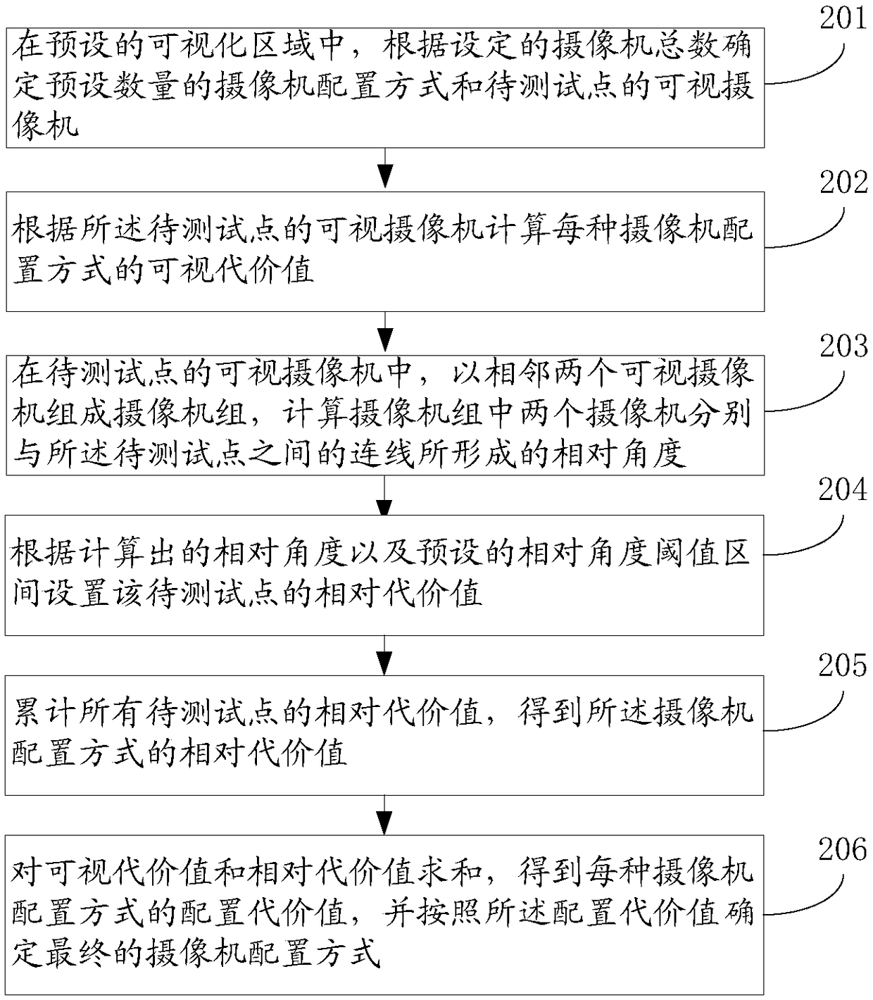
[0046] figure 2 It is a flow chart of a camera configuration method provided in Embodiment 2 of the present invention. The execution subject of this embodiment may be a computer device or a functional unit in the computer device. This embodiment specifically includes steps S201 to S206, which are described in detail as follows:

[0047] S201: In the preset visualization area, determine a preset number of camera configuration modes and visible cameras of the points to be tested according to the set total number of cameras.

[0048] The preset visualization area can be any size created by the user in the optical motion capture system, and contains the simulated area of ​​obstacles such as columns and walls. In the preset visualization area, users can further set camera parameters, including setting the total number of cameras, etc. Among them, the total number of cameras set can be actually adjusted.

[0049] The camera configuration mode can be determined according to the ca...

Embodiment 3

[0068] Figure 5 It is a flow chart of a camera configuration method provided by Embodiment 3 of the present invention. For Embodiment 3, refer to Embodiment 2. For step S301, refer to Step S201 in Embodiment 2, and details are not repeated here.

[0069] S302: Set the acquisition weight of the points to be tested.

[0070] Wherein, the collection weight identifies the influence of the collection weight of the point to be tested on the configuration cost value. That is to say, when calculating the configuration cost value of the camera configuration mode, in addition to considering the number of visible cameras at the point to be tested, the relative angle between two adjacent visible cameras at the point to be tested, etc., it is also considered Whether the point to be tested belongs to the set key acquisition space area (affects acquisition weight). Under normal circumstances, if the point to be tested belongs to the key collection space area, it means that the point to be...


PUM


Abstract

The invention provides a camera configuration method and device. The method comprises the following steps: determining a preset number of camera configuration modes and visual cameras of a to-be-tested point according to a set total number of cameras; calculating a relative cost value of each camera configuration mode according to the relative position relationship between two adjacent visible cameras of the to-be-tested point in each camera configuration mode; and calculating a configuration cost value of each camera configuration mode according to the relative cost value, and determining a final camera configuration mode according to the configuration cost value. In the camera configuration method and device provided by the embodiment of the invention, as the configuration cost value iscalculated according to the relative position relationship between two adjacent visible cameras of the to-be-tested point in each camera configuration mode, the calculated configuration cost value ismore reasonable, in this way, the configuration mode of the cameras is more reasonable, a proper number of motion capture cameras is configured more reasonably while the motion capture effect is ensured, and the configuration of the cameras is more economical and reasonable.

Description

technical field [0001] The invention relates to the field of computer vision, in particular to a camera configuration method and device. Background technique [0002] In the process of optical motion capture, the price of motion capture cameras is very expensive. It is very important to save costs by rationally configuring an appropriate number of motion capture cameras while ensuring the motion capture effect. Therefore, how to rationally configure an appropriate number of motion capture cameras has become an urgent problem to be solved. [0003] The prior art discloses a camera layout scheme. The idea of ​​the camera layout scheme is: first randomly generate a certain number of camera configurations, and then calculate the number of visible cameras for each point to be tested in each camera configuration, Finally, according to the number of visible cameras at each point to be tested, the configuration cost of each camera configuration is calculated. When calculating the ...

Claims


Application Information

Patent Timeline
Patent Type & Authority Applications(China)
IPC IPC(8): H04N5/247
CPCH04N23/90
Inventor 黄艳长坂友裕李拓许秋子
Owner SHENZHEN REALIS MULTIMEDIA TECH CO LTD
Why Eureka
Try Eureka