Immersion oil rust-protection device for mechanical parts
A technology for mechanical parts and bearings, applied in the field of oil-immersed anti-rust devices, can solve the problems of oil pollution, time-consuming and labor-intensive, labor-intensive, etc.
- Summary
- Abstract
- Description
- Claims
- Application Information
AI Technical Summary
Problems solved by technology
Method used
Image

Examples
Embodiment 1
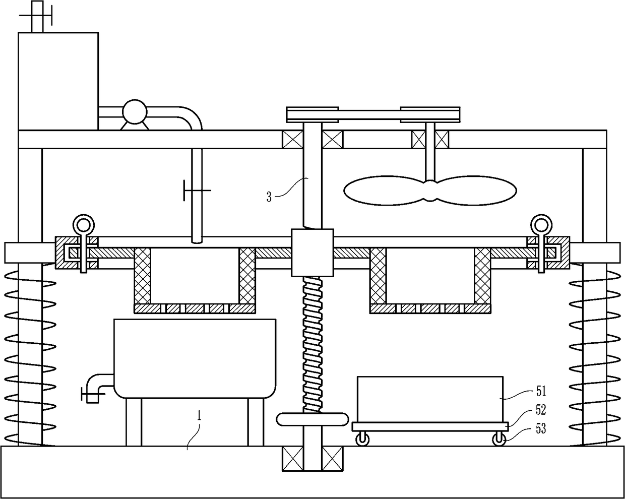
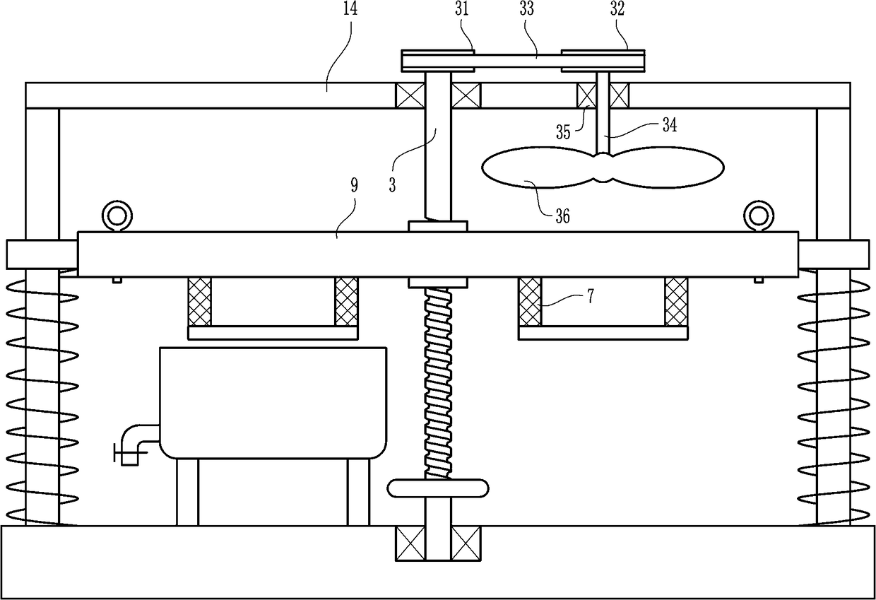
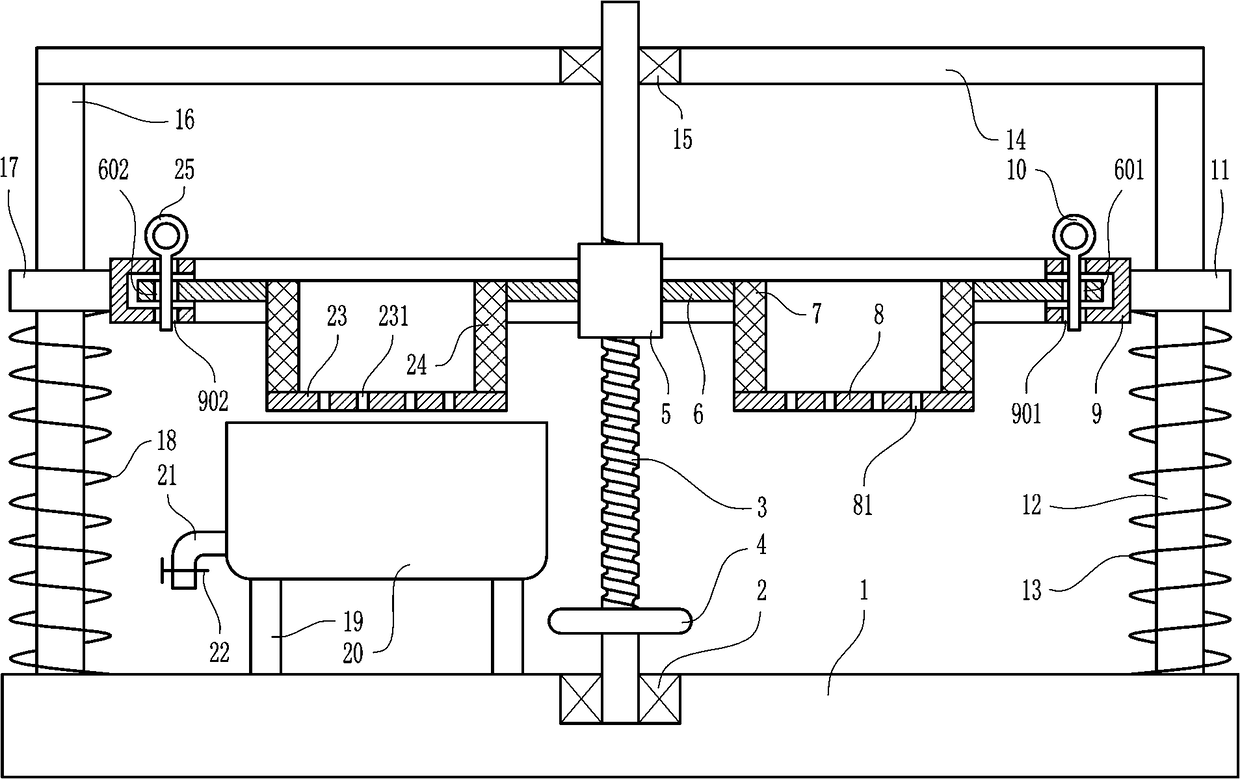
[0027] An oil-immersed anti-rust device for mechanical parts, such as Figure 1-5 As shown, it includes a base 1, a first bearing 2, a large screw rod 3, a rotating wheel 4, a large nut 5, a large rotating disk 6, a first drum sieve 7, a first tray 8, a ring-type concave plate 9, the first A pin rod 10, the first guide sleeve 11, the first support rod 12, the first spring 13, the top plate 14, the second bearing 15, the second support rod 16, the second guide sleeve 17, the second spring 18, supporting legs 19 , cylinder body 20, drain pipe 21, first valve 22, second tray 23, second trommel 24 and second pin rod 25, the middle position of the top of the base 1 is embedded with the first bearing 2, the large screw rod 3 The lower end of the shaft is connected with the first bearing 2 by interference, the rotating wheel 4 is fixedly set on the lower part of the large screw rod 3, the large nut 5 is arranged on the upper part of the large screw rod 3, the large nut 5 is matched w...
Embodiment 2
[0029] An oil-immersed anti-rust device for mechanical parts, such as Figure 1-5 As shown, it includes a base 1, a first bearing 2, a large screw rod 3, a rotating wheel 4, a large nut 5, a large rotating disk 6, a first drum sieve 7, a first tray 8, a ring-type concave plate 9, the first A pin rod 10, the first guide sleeve 11, the first support rod 12, the first spring 13, the top plate 14, the second bearing 15, the second support rod 16, the second guide sleeve 17, the second spring 18, supporting legs 19 , cylinder body 20, drain pipe 21, first valve 22, second tray 23, second trommel 24 and second pin rod 25, the middle position of the top of the base 1 is embedded with the first bearing 2, the large screw rod 3 The lower end of the shaft is connected with the first bearing 2 by interference, the rotating wheel 4 is fixedly set on the lower part of the large screw rod 3, the large nut 5 is arranged on the upper part of the large screw rod 3, the large nut 5 is matched w...
Embodiment 3
[0032] An oil-immersed anti-rust device for mechanical parts, such as Figure 1-5 As shown, it includes a base 1, a first bearing 2, a large screw rod 3, a rotating wheel 4, a large nut 5, a large rotating disk 6, a first drum sieve 7, a first tray 8, a ring-type concave plate 9, the first A pin rod 10, the first guide sleeve 11, the first support rod 12, the first spring 13, the top plate 14, the second bearing 15, the second support rod 16, the second guide sleeve 17, the second spring 18, supporting legs 19 , cylinder body 20, drain pipe 21, first valve 22, second tray 23, second trommel 24 and second pin rod 25, the middle position of the top of the base 1 is embedded with the first bearing 2, the large screw rod 3 The lower end of the shaft is connected with the first bearing 2 by interference, the rotating wheel 4 is fixedly set on the lower part of the large screw rod 3, the large nut 5 is arranged on the upper part of the large screw rod 3, the large nut 5 is matched w...
PUM
 Abstract
Description
Claims
Application Information
 - R&D
- Intellectual Property
- Life Sciences
- Materials
- Tech Scout
- Unparalleled Data Quality
- Higher Quality Content
- 60% Fewer Hallucinations
Browse by: Latest US Patents, China's latest patents, Technical Efficacy Thesaurus, Application Domain, Technology Topic, Popular Technical Reports.
© 2025 PatSnap. All rights reserved.Legal|Privacy policy|Modern Slavery Act Transparency Statement|Sitemap|About US| Contact US: help@patsnap.com