
Vertical vibration concentrating machine

A technology of concentrator and vibrating motor, which is applied in solid separation, filter screen, grid and other directions, can solve the problem of not having a block rotating structure and connecting rod scraper structure, uneven ore raw materials, and inability to achieve slag scraping And other issues

Inactive Publication Date: 2018-09-07
陈跃勇
View PDF0 Cites 9 Cited by
  • Summary
  • Abstract
  • Description
  • Claims
  • Application Information

AI Technical Summary

Problems solved by technology

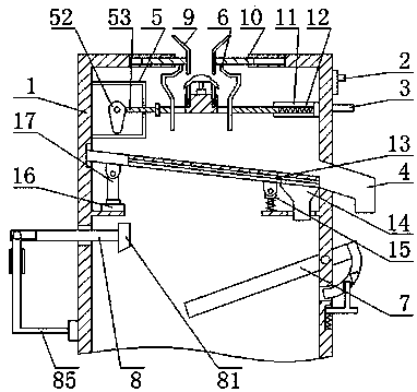
[0003] At present, the feeding method of the existing vertical vibrating concentrator is mostly to directly scatter the ore raw material on the sieve plate through a single feed port, which may easily cause the ore raw material to be scattered on the sieve plate not evenly. In addition, the surface of the slideway It is relatively easy to leave slag, and usually does not have a block rotation structure and a connecting rod scraper structure, so that the slag scraping on the surface of the slideway cannot be achieved

Method used


Image

  • Vertical vibration concentrating machine
  • Vertical vibration concentrating machine
  • Vertical vibration concentrating machine

Examples


Embodiment Construction

[0021] The following will clearly and completely describe the technical solutions in the embodiments of the present invention with reference to the accompanying drawings in the embodiments of the present invention. Obviously, the described embodiments are only some, not all, embodiments of the present invention. Based on the embodiments of the present invention, all other embodiments obtained by persons of ordinary skill in the art without making creative efforts belong to the protection scope of the present invention.

[0022] In describing the present invention, it should be understood that the terms "longitudinal", "transverse", "upper", "lower", "front", "rear", "left", "right", "vertical", The orientations or positional relationships indicated by "horizontal", "top", "bottom", "inner", "outer", etc. are based on the orientations or positional relationships shown in the drawings, and are only for the convenience of describing the present invention, rather than indicating or...


PUM


Abstract

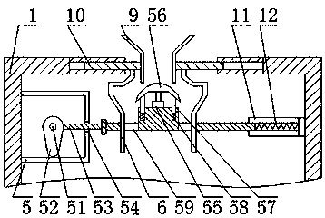
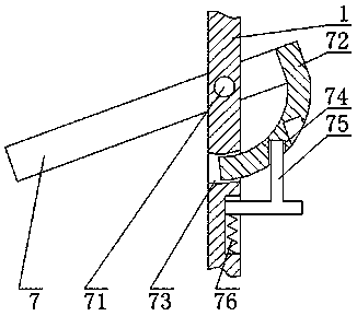
The invention discloses a vertical vibration concentrating machine which comprises a concentrating machine body. The surface of the right upper end of the concentrating machine body is provided with ashifting switch and a power line. The right side of the concentrating machine body is provided with a primary discharge outlet, a transmission box is arranged inside the left upper side of the concentrating machine body, a cam is rotationally connected with the interior of the transmission box through a motor, a guide plate is in sliding connection with the right surface of the cam, the middle ofthe guide plate is provided with a feeding separation port, flow guide plates are symmetrically arranged on the two sides of the middle of the guide plate, a sliding plate is fixedly connected to thesurface of the upper end of the flow guide plate, the concentrating machine body is in sliding connection with the outer surface of the left side of the sliding plate, a feeding hopper is fixedly connected to the surface of the right end of the sliding plate, a sliding way is rotationally connected with the interior of the right lower side of the concentrating machine body through a first rotating shaft, and a first vibration motor is arranged inside the left side of the concentrating machine body. According to the vertical vibration concentrating machine, ore raw materials are scattered on asieve plate by being divided into left and right portions, and ore slag on the surface of the sliding way is scratched away.

Description

technical field [0001] The invention relates to the field of mineral concentrator equipment, in particular to a vertical vibration concentrator. Background technique [0002] Mineral dressing is based on the physical and chemical properties of different minerals in the ore. After the ore is crushed and ground, gravity separation, flotation, magnetic separation, electric separation, etc. are used to separate the useful minerals from the gangue minerals. Various symbiotic useful minerals are separated from each other as much as possible, and harmful impurities are removed or reduced to obtain raw materials for smelting or other industries. [0003] At present, the feeding method of the existing vertical vibrating concentrator is mostly to directly scatter the ore raw material on the sieve plate through a single feed port, which may easily cause the ore raw material to be scattered on the sieve plate not evenly. In addition, the surface of the slideway It is relatively easy to...

Claims


Application Information

Patent Timeline
IPC IPC(8): B07B1/28B07B1/42B07B1/46
CPCB07B1/28B07B1/42B07B1/4609B07B1/4663B07B2201/04
Inventor 陈跃勇
Owner 陈跃勇
Learn More