
Auto parts grinding device

A technology for auto parts and racks, which is applied in the direction of grinding drive devices, grinding/polishing safety devices, grinding machines, etc., which can solve the problems of non-replacement, reduced hardness of the grinding head, and long stay, so as to save time for changing positions , Guarantee the quality of grinding and reduce the difficulty of rotation

Active Publication Date: 2019-11-05
宁波隆锐机械制造有限公司
View PDF1 Cites 0 Cited by
  • Summary
  • Abstract
  • Description
  • Claims
  • Application Information

AI Technical Summary

Problems solved by technology

[0004] The above scheme solves the problems in the prior art by providing a cavity in the grinding head and a cooling medium in the cavity, so that the grinding head can dissipate heat when grinding, but the above scheme still has the following problems: The medium is enclosed in the cavity, and its total amount is fixed. Although it can achieve a certain heat dissipation effect, after a period of grinding, the heat on the grinding head will accumulate more and more, and there will still be a large amount of heat that cannot be dissipated in time. It will still cause the hardness of the grinding head to decrease due to high temperature; the accessories cannot be changed to the grinding position. It is necessary to stop grinding after the grinding device has polished one side of the accessory, and the operator can change the position of the accessory to completely polish the entire accessory. Long stay in the middle, low efficiency

Method used


Image

  • Auto parts grinding device

Examples


Embodiment Construction

[0018] Further detailed explanation through specific implementation mode below:

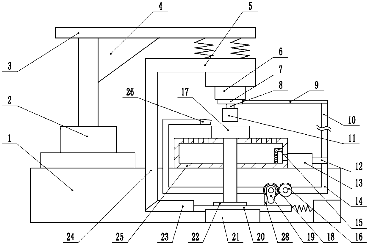
[0019] The reference signs in the drawings of the description include: frame 1, hydraulic cylinder 2, workbench 3, triangular plate 4, support plate 5, motor 6, ring pipe 7, rotating shaft 8, connecting pipe 9, hose 10, grinding head 11. Air outlet pipe 12, negative pressure pump 13, branch pipe 14, filter cover 15, fan gear 16, fixed seat 17, gear 18, cam 19, slide bar 20, chute 21, ratchet 22, second wedge bar 23, first A wedge bar 24, collection box 25, nozzle 26.

[0020] The embodiment is basically as attached figure 1 Shown: The auto parts grinding device includes a frame 1, on which a hydraulic cylinder 2 is threaded through bolts, and a workbench 3 is welded on the output shaft of the hydraulic cylinder 2, and the connection between the workbench 3 and the output shaft of the hydraulic cylinder 2 A triangular plate 4 is welded between them, a support plate 5 is arranged under the workbe...


PUM


Abstract

The invention discloses a grinding device for automobile accessories. The grinding device comprises a frame. A support plate is arranged below a workbench. A circular ring tube is fixed on the supportplate. A rotating shaft is rotationally connected in the inner circle of the circular ring tube. A through hole is formed in the rotating shaft. An open hole is formed in the circular ring tube. A grinding head is fixed on the rotating shaft. Radiating holes are formed in the grinding head. The through hole is communicated with the radiating holes. A connecting pipe is connected to the circular ring tube. A collecting box is fixed on the frame. Collecting holes are uniformly distributed in the collecting box. A rotating rod is rotationally connected to the collecting box. A fixing seat is fixed on the rotating rod. A negative-pressure pump is fixed on the frame. The negative-pressure pump is communicated with the collecting box. The negative-pressure pump is communicated with a gas outletpipe. A driving mechanism is arranged on the frame. Compared with the prior art, by the adoption of the scheme, the gas output by the negative-pressure pump can carry heat generated by the grinding accessories out of the grinding head, the hardness of the grinding head cannot be reduced, and therefore the grinding quality is ensured; and through the driving mechanism, the accessories rotate intermittently, and the grinding efficiency is greatly improved.

Description

technical field [0001] The invention belongs to the field of accessory grinding equipment, in particular to an auto accessory grinding device. Background technique [0002] Auto parts are a product of each unit that constitutes the whole car; most auto parts are stamped parts that are integrally formed. After the parts are stamped, there will be many burrs on the parts. The operator will polish the burrs to achieve the use Requirements: Generally, manual grinding is used to deal with burrs. During the grinding process, the grinding degree of parts is not well controlled, which also leads to unstable grinding quality, and a large amount of heat will be generated during the grinding process. If the heat is not If it is released in time, the temperature of the grinding head will be too high and the hardness will be reduced. The hard burrs on the accessories will react on the surface of the grinding head, making the surface of the grinding head uneven, which not only reduces the...

Claims


Application Information

Patent Timeline
Patent Type & Authority Patents(China)
IPC IPC(8): B24B9/04B24B41/02B24B41/06B24B55/02B24B27/00B24B55/00B24B41/04B24B47/06B24B55/06
CPCB24B9/04B24B27/0015B24B41/02B24B41/04B24B41/06B24B47/06B24B55/00B24B55/02B24B55/06
Inventor 卢文斌
Owner 宁波隆锐机械制造有限公司
Learn More