
Electric spark assisted ultrasonic vibration turning combined machining equipment and method

A technology of ultrasonic vibration and combined processing, which is applied in the field of turning processing, and can solve problems such as low processing efficiency, poor processing surface quality, and large wear of turning tools

Pending Publication Date: 2021-05-18
HUNAN UNIV OF SCI & TECH
View PDF0 Cites 0 Cited by
  • Summary
  • Abstract
  • Description
  • Claims
  • Application Information

AI Technical Summary

Problems solved by technology

[0002] At present, turning processing technology is the foundation of the field of mechanical processing. Turning is to drive the cutting tool to move through the lathe to turn the outer surface of the workpiece. The common method is to turn by contacting the turning tool with the surface of the workpiece. larger
Especially when turning difficult-to-machine metal materials, not only the wear on the turning tool is large, but also the processing efficiency is low, and the processing surface quality is poor. equipment to meet actual needs

Method used


Image

  • Electric spark assisted ultrasonic vibration turning combined machining equipment and method
  • Electric spark assisted ultrasonic vibration turning combined machining equipment and method
  • Electric spark assisted ultrasonic vibration turning combined machining equipment and method

Examples


Embodiment Construction

[0048]The present application will be further described in conjunction with the accompanying drawings in conjunction with the accompanying drawings.

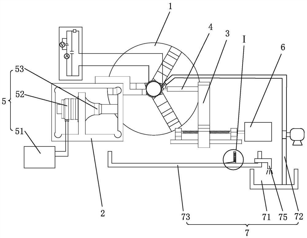
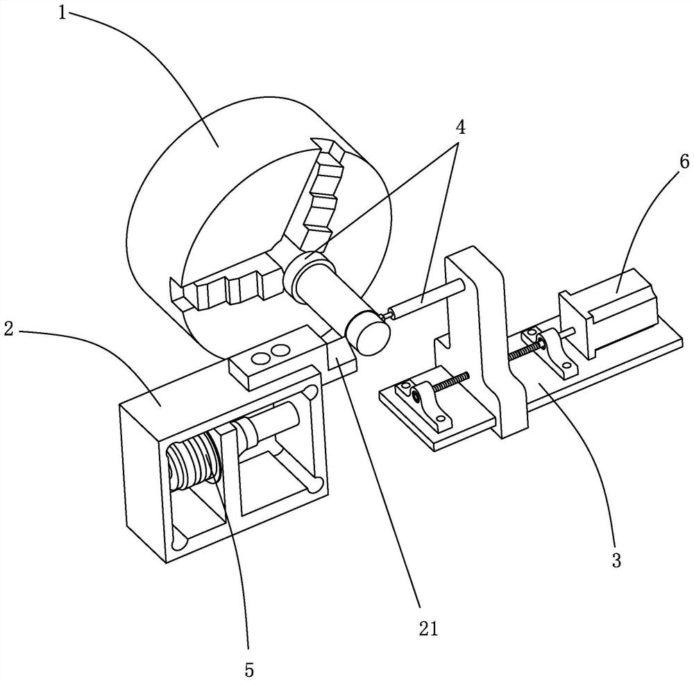
[0049]Such asFigure 1 ~ 8As shown, an electro-fire-assisted ultrasonic vibrating vehicle cutting process, including machine tools, chuck 1, moving turning device 2, mounting bracket 3, discharge heating device 4, ultrasonic generating device 5.

[0050]Specifically, the chuck 1 is disposed on the machine for a clip workpiece; the moving turning device 2 is provided on the upper side of the machine and is used for mobile vehicle cutting parts; the mobile turning device 2 There is a tool 21 for turning workpieces; the mounting bracket 3 is disposed on the other side of the machine, and is connected to the moving turning device 2, which is moved from the moving turning device 2; the discharge heating The device 4 is provided on the mounting bracket 3 for energizing to discharging the heating workpiece; the ultrasonic generating device 5 is dis...


PUM


Abstract

The invention discloses electric spark assisted ultrasonic vibration turning combined machining equipment. The electric spark assisted ultrasonic vibration turning combined machining equipment comprises a machine tool, a chuck arranged on the machine tool, a movable turning device which is arranged on one side of the upper portion of the machine tool and provided with a tool, an installation support which is arranged on the other side of the upper portion of the machine tool and connected with the movable turning device, a discharge heating device arranged on the installation support, and an ultrasonic generation device arranged on the movable turning device. The invention further discloses an electric spark assisted ultrasonic vibration turning combined machining method. According to the electric spark assisted ultrasonic vibration turning combined machining equipment and method, a workpiece can be turned while being discharged and heated, and therefore the workpiece can be heated and softened, the turning difficulty of turning the workpiece through a turning tool is lowered, the loss of the tool can be reduced so that the service life of the tool can be prolonged, the machining efficiency can be improved, and the efficient and precise turning effect can be achieved; and meanwhile, the tool can do high-frequency periodic vibration motion through the ultrasonic generation device, and therefore the prominent effects that the tool breaks chips, the cutting heating phenomenon is reduced, and the cutting force is reduced are achieved.

Description

Technical field[0001]The present application relates to the technical field of turning machining, and in particular, it is to relate to an electric spatula-assisted ultrasonic vibrator composite processing apparatus, and an electro-fire-assisted ultrasonic vibration vehicle cutting process.Background technique[0002]At present, turning processing technology is the basis of the field of machining. Turning is to move the cutting tool by the lathe to take turning on the outer surface of the workpiece. The common means is to turn in contact with the workpiece surface, so the resistance generated during the turning process. Larger. In particular, when the metal material is machined in the car, not only the wear of the car knife is large, and the processing efficiency is low, the surface quality is poor, and the technical personnel, which will be urgently needed to develop an electric fire-assisted ultrasonic vibration vehicle cutting composite processing. Equipment to meet the actual need...

Claims


Application Information

Patent Timeline
IPC IPC(8): B23B25/00B23Q11/00
CPCB23B25/00B23Q11/00B23H7/38B23H7/26B23H1/02B23H11/003B23Q11/1076B23Q11/1069B23H2400/00B23B2270/10
Inventor 李常平黄磊高泰祖李树健李鹏南牛秋林邱新义
Owner HUNAN UNIV OF SCI & TECH
Learn More