Seamless curved bridge adopting semi-rigid integral abutments

An integral bridge abutment and seamless curved bridge technology, applied in the direction of bridges, bridge parts, bridge construction, etc., can solve the problems such as the damage of the shockproof block and the poor seismic performance of the seamless curved bridge, so as to improve the seismic performance and solve the horizontal problem. Bridge shear force and deformation, simple effect of structural design

Pending Publication Date: 2018-09-07
FUJIAN UNIV OF TECH
View PDF12 Cites 1 Cited by
  • Summary
  • Abstract
  • Description
  • Claims
  • Application Information

AI Technical Summary

Problems solved by technology

Although the strapping plate can restrain the main girder, due to the bending and torsion coupling force characteristics of the curved bridge, under the load and temperature changes of the main girder, the junction of the main girder and the strappin...

Method used


Image

  • Seamless curved bridge adopting semi-rigid integral abutments
  • Seamless curved bridge adopting semi-rigid integral abutments

Examples


Embodiment 1

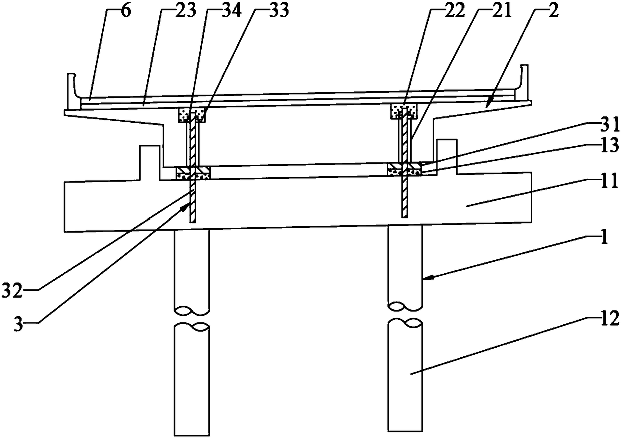
[0054] Please refer to figure 2 As shown, a seamless curved bridge using a semi-rigid integral abutment includes an abutment 1, a main girder 2 and a semi-rigid structure 3 connecting the abutment 1 and the main girder 2, and the abutment 1 It includes a platform cap 11 and a pile foundation 12 arranged under the platform cap 11, the platform cap 11 is provided with a groove opening upward, and the groove is provided with a supporting pad stone 13, and the main beam The lower end of 2 is provided with a protrusion suitable for the groove, and the main beam 2 is arranged on the support pad stone 13 of the groove through the protrusion;

[0055] The semi-rigid structure 3 includes a rubber cushion 31, a steel rod 32, a steel plate 33 and a bolt 34, and the rubber cushion 31 is arranged between the support pad stone 13 and the main beam 2; the steel rod 32 runs through the rubber pad 31 and the support stone 13 and the lower end of the steel rod 32 is inserted into the table ca...

Embodiment 2

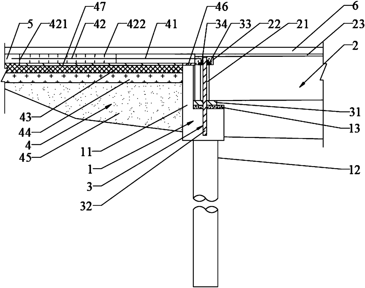
[0060] It is the same as other structures of the seamless curved bridge using semi-rigid integral abutment in Embodiment 1, the difference is that the seamless curved bridge using semi-rigid integral abutment also includes a rear wiring system 4, and the rear The wiring system 4 includes a horizontally arranged board 41, a transition board 42, a base layer located below the board 41 and the transition board 42, and a backfill layer 45. One end of the board 41 and the main beam 2 connection, the other end of the strapping plate 41 is connected to one end of the transition plate 42, the other end of the transition plate 42 is connected to the external wiring line surface 5, and the base layer includes roller compacted concrete base layers 43 and A graded crushed stone cushion layer 44 , and the backfill layer 45 is arranged below the graded crushed stone cushion layer 44 .

[0061] A rubber sliding layer 46 is provided between the board 41 and the back wall of the platform cap 1...


PUM


Abstract

The invention relates to the field of bridge construction, in particular to a seamless curved bridge adopting semi-rigid integral abutments. The seamless curved bridge comprises the abutments, a girder and semi-rigid structures connecting the abutments with the girder, each abutment comprises an abutment cap and a pile foundation arranged below the abutment cap, a groove with an upward opening isformed in each abutment cap, a support cushion stone is arranged in each groove, protrusions matched with the grooves are arranged at the lower end of the girder, and the girder is arranged on the support cushion stones of the grooves through the protrusions; and each semi-rigid structure comprises a rubber spacer, a steel rod, a steel plate and bolts, and each rubber spacer is arranged between the corresponding support cushion stone and the girder. The seamless curved bridge has the beneficial effects that the structural design is simple, transverse bridge direction shearing force and deformation generated in the jointing position of the girder and a lap-joint plate can be effectively avoided, and the anti-seismic performance of the seamless curved bridge can be improved as well.

Description

technical field [0001] The invention relates to the field of bridge construction, in particular to a seamless curved bridge using a semi-rigid integral abutment. Background technique [0002] Curved bridges have been widely used in high-grade highways, urban viaducts and overpasses in my country. The main girder bears complex forces. In addition to bearing bending moment and shear force, there is also a large torque; In addition to the deformation in the long direction (longitudinal bridge direction), there are also deformations in the sagittal height direction (transverse bridge direction) and torsional warping deformation. [0003] The seamless curved bridges that have been built in our country are mainly extended deck bridges. The slab is connected with the main girder as a whole, and the telescopic device is cancelled. However, the main girder and the abutment cap are still connected by supports. Although the strapping plate can restrain the main girder, due to the bendi...

Claims


Application Information

Patent Timeline
IPC IPC(8): E01D19/02E01D19/06
CPCE01D19/02E01D19/06
Inventor 林上顺查雄栋胡发林彭逸涵林昭峰欧智菁
Owner FUJIAN UNIV OF TECH
Why Eureka
Try Eureka