Installing and adjusting method for collimation type solar simulator optical system

A solar simulator and optical system technology, applied in the field of optical system installation and adjustment, can solve problems such as low utilization rate of light energy, influence on light uniformity efficiency of optical integrator, and poor uniformity of solar simulator radiation, so as to improve simulation accuracy and ensure Consistency of optical axis, improvement of light energy utilization rate and uniformity of irradiation

Active Publication Date: 2018-09-07
CHANGCHUN UNIV OF SCI & TECH
View PDF8 Cites 10 Cited by
  • Summary
  • Abstract
  • Description
  • Claims
  • Application Information

AI Technical Summary

Problems solved by technology

[0004] In order to overcome the inconsistency between the optical axis of the ellipsoidal condenser and the optical axis of other components in the optical system in the existing collimating solar simulator optical system, the resulting low utilization rate of light ener...

Method used


Image

  • Installing and adjusting method for collimation type solar simulator optical system
  • Installing and adjusting method for collimation type solar simulator optical system
  • Installing and adjusting method for collimation type solar simulator optical system

Examples


Embodiment 1

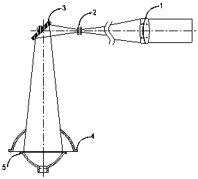
[0029] figure 1An optical system of a collimating solar simulator provided by an embodiment of the present invention. Wherein, wherein, an optical integrator 2 is arranged in front of the collimating objective lens 1, and the optical integrator 2 is placed at the second focal point of the ellipsoidal condenser 5, and a turning plane reflector 3 is set in front of the optical integrator 2, and a turning plane reflector 3 is arranged in front of the optical integrator 2 A spherical reflector 4 is arranged below the spherical reflector 4, and an ellipsoidal condenser 5 is arranged below the spherical reflector 4. The center of the spherical reflector 4 coincides with the first focus of the ellipsoidal condenser 5.

[0030] The ellipsoidal condenser 5 and the spherical reflector 4 are used to converge the light emitted by the light source to improve the energy utilization rate of the light source, thereby improving the simulation value of the radiation intensity of the simulator; ...


PUM


Abstract

The invention discloses an installing and adjusting method for a collimation type solar simulator optical system. A reference optical axis is established through a theodolite I and a theodolite II, and a pentaprism, a guide rail, a tool reflector and a laser device are matched to conduct installing and adjusting capable of guaranteeing optical axis consistency on a collimator objective, an opticalintegrator, a steering plane reflector, a spherical reflector and an ellipsoid collecting lens, and the light energy utilization rate and irradiation uniformity of a collimation type solar simulatorcan be effectively improved.

Description

technical field [0001] The invention relates to a method for installing and adjusting an optical system, in particular to a method for installing and adjusting an optical system of a collimating solar simulator. Background technique [0002] According to different optical systems, solar simulators can be divided into coaxial diverging system and coaxial collimating system. The former has a relatively simple structure, lower cost than the latter, and high utilization rate of light energy. However, since there is no collimating objective lens, the output The light beam is not collimated, and is suitable for occasions without collimation requirements; the latter is relatively expensive, using a collimating objective lens, and placing a field diaphragm at the focal plane of the collimating objective lens, by changing the field light The size of the diaphragm can simulate different collimation angles of the sun, which has high uniformity and is widely used, but the light energy u...

Claims


Application Information

Patent Timeline
IPC IPC(8): F21V13/00
CPCF21V13/00
Inventor 刘石张健孙高飞张国玉
Owner CHANGCHUN UNIV OF SCI & TECH
Why Eureka
Try Eureka