
Correction method of electronic compass

An electronic compass and correction method technology, applied in compass, measuring device, surveying and navigation, etc., can solve the problem of no error compensation parameter re-correction function, inability to compensate for soft magnetic interference and hard magnetic interference, and complicated calibration.

Pending Publication Date: 2018-09-07
SOUTHWEST INST OF APPLIED MAGNETICS
View PDF7 Cites 22 Cited by
  • Summary
  • Abstract
  • Description
  • Claims
  • Application Information

AI Technical Summary

Problems solved by technology

[0005] First, it only has the functions of processing, displaying, storing or transmitting the earth's magnetic field and gravitational acceleration signals, and does not have the error correction function of external signals
[0006] Second, it does not have the function of re-correcting the error compensation parameters embedded in the microprocessor through the communication interface. It is cumbersome to install in the whole system for calibration, and it is not suitable for long-term unattended and inconvenient mobile systems.
If the product is installed in a position where rotation and rotation cannot occur, the calibration cannot be completed, and the electronic compass must be disassembled here, which is very inconvenient
Even if the product is disassembled, the electronic compass can be calibrated by rotating it alone, which cannot compensate for the soft and hard magnetic interference caused by the carrier platform to the electronic compass

Method used


Image

  • Correction method of electronic compass
  • Correction method of electronic compass
  • Correction method of electronic compass

Examples


Embodiment 1

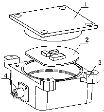
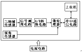
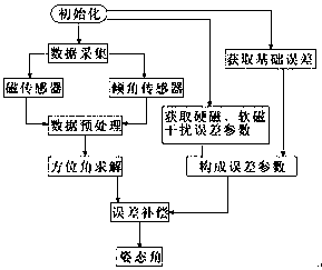
[0054] Embodiment 1: see Figure 1 to Figure 6, a method for correcting an electronic compass, comprising an electronic compass, the electronic compass comprising a housing body, a cover plate and a circuit unit located in the housing body, the circuit unit comprising a data acquisition circuit, a microprocessor, a serial port communication circuit and a power supply circuit , the data acquisition circuit includes a three-axis magnetic sensor and an inclination sensor, the three-axis magnetic sensor is used to obtain the earth's three-axis geomagnetic field value of the current environment, and sends it to the microprocessor after the signal conditioning circuit and the A / D conversion circuit Among them, the inclination sensor is used to obtain the earth’s gravitational acceleration value in the current environment, and convert it into an inclination value and send it to the microprocessor. The serial port of the microprocessor is connected to the serial port communication circ...

Embodiment 2

[0089] Embodiment 2: In the prior art, the electronic compass has an internal autonomous correction mode instruction. Before solving the azimuth angle, first add a part of judgment. The upper computer inputs the command "whether correction is required". Calibration, enter the internal self-calibration mode command:

[0090] It is necessary to keep the product attitude angle less than 15° and slowly rotate, and the rotation range exceeds 360° to achieve product calibration; during this period, the calibration program embedded in the microprocessor is used to execute the program of collecting sensor data. The collected data mainly includes "after data preprocessing "The magnetic field data and inclination angle data in the link, when the number of collected points is sufficient, the error parameters are solved and stored through the embedded correction algorithm processing and correction parameter solving process; then continue to run the azimuth angle solving, error compensatio...

Embodiment 3

[0099] Embodiment 3: see Figure 7 , It can be seen from Embodiment 2 that there is a major defect here, that is, the carrier cannot be rotated after installation, and the internal calibration procedure cannot be realized.

[0100]At this time, before solving the azimuth angle, first add the first judgment, the upper computer inputs the command "whether correction is required", after the microprocessor receives it, if no correction is required, directly use the pre-stored error parameters combined with the azimuth angle solution to solve the attitude Angle information, if it needs to be corrected, enter the next judgment, whether to correct by external auxiliary correction mode command or internal self-correction mode command, we set the external auxiliary correction mode command as mode 1, and the internal self-correction mode command as mode 2, if adopt Mode 1 is used for correction, see Example 1 for the specific method, and if Mode 2 is used for correction, see Example 2.


PUM


Abstract

The invention discloses a correction method of an electronic compass. The correction method comprises the following steps: (1), acquiring basic error parameters, acquiring geomagnetic field data and inclination data of a current environment through a magnetism sensor and an inclination sensor respectively, and sending into a microprocessor; (2), performing inclination compensation on the magneticfield data; (3), performing azimuth solution according to the data obtained in the step (2); (4), acquiring a hard magnetic interference error parameter and a soft magnetic interference error parameter on a mounting site, and forming error parameters together with the basic error parameters; (5), performing error compensation on the data obtained in the step (3) by using the error parameters to obtain attitude angle data; (6), with the combination of an attitude position compensation method, translating a coordinate origin of an actual coordinate system to an origin of a measuring coordinate system. By the correction method, the problem that the conventional electronic compass only has an attitude position information providing output function is solved; and by virtue of attitude information provided by itself, attitude position compensation is studied while an original hardware system architecture is not changed.

Description

technical field [0001] The invention relates to a method for testing a compass, in particular to a method for correcting an electronic compass. Background technique [0002] As a geomagnetic navigation module, the electronic compass is an important navigation tool that uses the earth's magnetic field and gravitational acceleration to measure the direction. It outputs measured values ​​such as azimuth, attitude angle, and magnetic field values. , simple structure, low power consumption, low cost and other advantages, it is widely used in aviation, navigation, vehicle positioning, geological exploration and other fields. [0003] Traditional electronic compass hardware system mainly includes magnetic sensor, inclination sensor, signal conditioning circuit, A / D conversion circuit, microprocessor, power supply circuit, serial port communication circuit, software system mainly includes data acquisition, azimuth solution, error parameter calculation, error compensate. The main f...

Claims


Application Information

Patent Timeline
Patent Type & Authority Applications(China)
IPC IPC(8): G01C17/32G01C17/38
CPCG01C17/32G01C17/38
Inventor 彭根斋白雪王福均闫欢尹久红
Owner SOUTHWEST INST OF APPLIED MAGNETICS
Learn More