Improved bridge monitoring device

A monitoring device and improved technology, applied in traffic control system, position/direction control, non-electric variable control and other directions, can solve the problems of increased mains power consumption, unadjustable angle, low solar energy conversion rate, etc., to achieve convenient operation, The effect of increasing service life and simple structure

Inactive Publication Date: 2018-09-07
刘永达
View PDF2 Cites 1 Cited by
  • Summary
  • Abstract
  • Description
  • Claims
  • Application Information

AI Technical Summary

Problems solved by technology

[0002] Monitoring devices will be installed on some bridges to monitor the passing vehicles to increase the safety of bridge traffic, while traditional bridge monitoring devices mostly work with the mains, which greatly increases the consumption of the mains. There are also some monitoring equipment powered by photovoltaics, but most of the photovoltaic panels are fixed and their angles cannot be adjusted, resulting in low solar conversion rates.

Method used


Image

  • Improved bridge monitoring device
  • Improved bridge monitoring device
  • Improved bridge monitoring device

Examples


Embodiment Construction

[0015] Combine below Figure 1-4 The present invention will be described in detail.

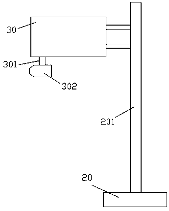
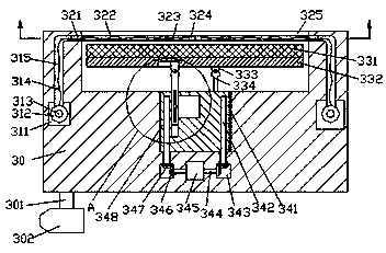
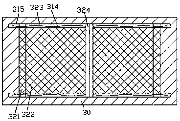
[0016] refer to Figure 1-4 , an improved bridge monitoring device according to an embodiment of the present invention, comprising a support rod 201 with a machine base 20 at the bottom, an assembly frame 30 fixedly arranged on the upper left side of the support rod 201 and fixedly installed on the The monitor 302 at the left bottom of the assembly frame 30 is provided with an installation cavity 325 in the top end surface of the assembly frame 30, and the upper side of the inner walls of the front and rear sides of the installation cavity 325 is correspondingly provided with a first sliding cavity 323, the inner walls of the left and right sides of the installation cavity 325 are correspondingly provided with the drawing grooves 321 connected to the first sliding chamber 323, and the outer sides of the drawing grooves 321 are respectively provided with passing grooves 315. The bottom of th...


PUM


Abstract

The invention relates to an improved bridge monitoring device. The device comprises a supporting rod, an assembling frame, and a monitor; a base is arranged at the bottom of the supporting rod; the assembling frame is fixedly disposed at the upper part of the left side of the supporting rod; the monitor is fixedly mounted at the bottom of the left side of the assembling frame through a connectingarm; a mounting cavity is formed in the top end surface of the assembling frame; first sliding cavities are formed at the upper sides of the front side inner wall and the rear side inner wall of the mounting cavity respectively; drawing-pulling slots communicated with the first sliding cavities are correspondingly formed in the left side inner wall and right side inner wall of the mounting cavity;passage grooves are formed at the external side of each drawing-pulling slot, wherein the passage grooves are corresponding to each other in an anterior-posterior direction; first rotation cabins communicated with the the tails of the bottom extension ends of the passage grooves are formed at the tails of the bottom extension ends of the passage grooves; a guided conveying rod is movably mountedin the first sliding cavities between the front side and rear side of the mounting cavity; pull ropes are fixedly mounted in the first sliding cavities outside the guided conveying rod; the pull ropessequentially extend into the passage grooves and the first rotation cabins and are fixedly connected with winding cylinders in the first rotation cabins; and a first rotating rod is fixedly mounted between the front winding cylinder and the rear winding cylinder.

Description

technical field [0001] The invention relates to the field of bridges, in particular to an improved bridge monitoring device. Background technique [0002] Monitoring devices will be installed on some bridges to monitor the passing vehicles to increase the safety of bridge traffic, while traditional bridge monitoring devices mostly work with the mains, which greatly increases the consumption of the mains. There are also some monitoring equipment powered by photovoltaics, but most of the photovoltaic panels are fixed, and their angles cannot be adjusted, resulting in low solar conversion rates. Contents of the invention [0003] The object of the present invention is to provide an improved bridge monitoring device for overcoming the above-mentioned defects in the prior art. [0004] An improved bridge monitoring device according to the present invention, comprising a support rod with a machine base at the bottom, an assembly frame fixedly arranged above the left side of the...

Claims


Application Information

Patent Timeline
Patent Type & Authority Applications(China)
IPC IPC(8): G05D3/10G08G1/00H02S20/32
CPCG05D3/105G08G1/00H02S20/32Y02E10/50
Inventor 刘永达
Owner 刘永达
Why Eureka
Try Eureka