Multi-work-condition rotary machine fault diagnosis method

A technology for rotating machinery and fault diagnosis, which is applied in the testing of machines/structural components, instruments, and data processing applications. It can solve problems such as frequent faults, difficult manual diagnosis, strong nonlinearity, etc., and achieve enhanced extraction capabilities and improved classification. Accuracy, the effect of improving linear separability

Active Publication Date: 2018-09-07
TONGJI UNIV
View PDF4 Cites 22 Cited by
  • Summary
  • Abstract
  • Description
  • Claims
  • Application Information

AI Technical Summary

Problems solved by technology

Most of them work under complex or even harsh working conditions, so failures occur relatively frequently
Under different working conditions, the same fault type of rotating machinery often shows different time domain characteristics and frequency domain characteristics, and its strong nonlinearity brings great difficulties to manual diagnosis

Method used


Image

  • Multi-work-condition rotary machine fault diagnosis method
  • Multi-work-condition rotary machine fault diagnosis method
  • Multi-work-condition rotary machine fault diagnosis method

Examples


Embodiment 1

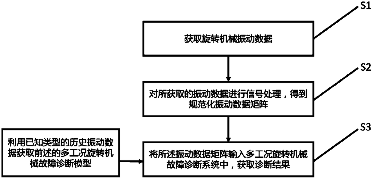
[0032] Such as figure 1 As shown, a multi-condition rotating machinery fault diagnosis method, including:

[0033] S1. Collect and obtain the original time-domain vibration data matrix of the rotating machinery;

[0034] S2. Perform Fourier transform and normalization processing on the original time-domain vibration data matrix in turn to obtain a normalized amplitude-frequency vibration data matrix;

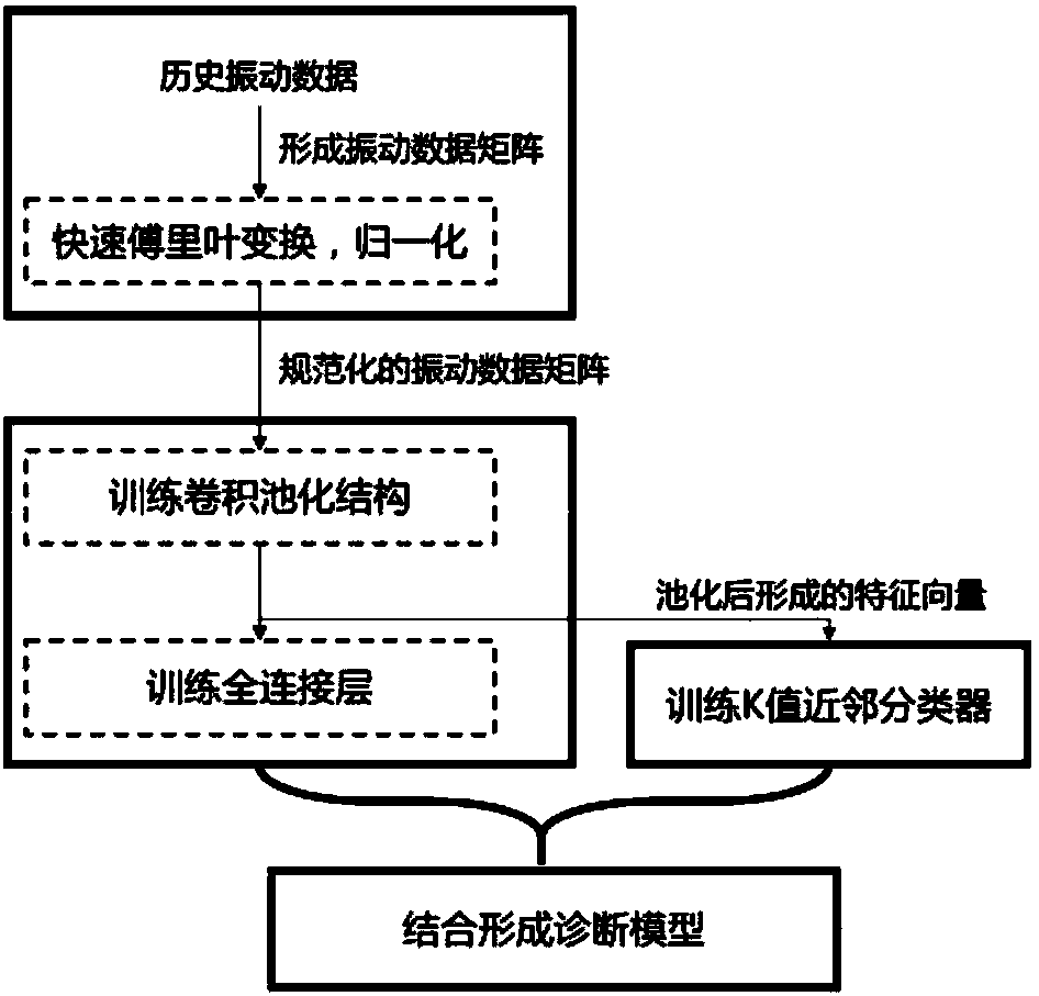
[0035] S3. Input the normalized amplitude-frequency vibration data matrix into the fault diagnosis model established by the serial combination of the convolutional neural network and the K-nearest neighbor classifier, and obtain the diagnosis result.

[0036] The process of step S1 specifically includes collecting the original time-domain vibration signals at the vibration monitoring points of the rotating machinery. The vibration monitoring points include rolling bearings, motor rotors, couplings, gears, etc. related structures, such as bearing supports, gearbox covers, etc. ...

Embodiment 2

[0076] This embodiment will further refine the description of the technical solution in combination with specific data, as follows:

[0077] S1. Collect the original vibration data matrix of the rotating machinery. In this embodiment, collect the original time-domain vibration signals at the vibration monitoring points of the rotating machinery, and arrange the time-domain vibration data into a time-domain vibration data matrix according to the sampling channels:

[0078]

[0079] In this embodiment, the single-channel radial vibration of the rolling bearing is used as the vibration data. Among them, a set of time domain vibration data contains 3 power frequency cycles, the sampling frequency is 12kHz, and the sampling time is 0.1s. According to the number of channels, the dimension of the time-domain vibration data matrix formed by it is 1×1200.

[0080] S2. Perform Fourier transform and normalization processing on the original vibration data in sequence to obtain a norma...


PUM


Abstract

The invention relates to a multi-work-condition rotary machine fault diagnosis method. The method includes the following steps that: S1, the original vibration data matrix of a rotary machine are acquired; S2, Fourier transformation and normalization processing are sequentially performed on the original vibration data, so that a normalized vibration data matrix can be obtained; and S3, the normalized vibration data matrix is inputted into a fault diagnosis model, so that a diagnosis result is obtained, wherein the fault diagnosis model is established by means of the series connection of a convolutional neural network and a K-nearest neighbor classifier. According to the method of the present invention, the capacity of the diagnostic model to extract invariant features under variable work conditions can be enhanced by means of the convolutional neural network; the classification capacity and robustness of the diagnostic model for nonlinear fault features can be improved by means of theK-nearest neighbor classifier; and on the basis of the convolutional neural network and the K-nearest neighbor classifier, the accuracy of the diagnostic model in the fault diagnosis of the rotary machine under complex working conditions can be improved, and powerful support can be provided for online intelligent fault diagnosis.

Description

technical field [0001] The invention relates to the technical field of mechanical fault diagnosis, in particular to a multi-working-condition rotating mechanical fault diagnosis method. Background technique [0002] With the advancement of technology, the complexity of mechanical equipment and industrial systems is increasing. Mechanical fault diagnosis technology has opened up a new way to improve the reliability, maintainability and effectiveness of equipment and systems. As far as industrial production is concerned, once certain production processes fail, it is easy to cause the paralysis of the entire production process, causing huge economic losses, and even threatening the safety of workers. Therefore, modern industry requires rapid and effective treatment at the beginning of the failure to maintain the normal operation of equipment and systems, minimize losses and reduce threats. Using computer to monitor equipment and system status to detect and locate faults in ti...

Claims


Application Information

Patent Timeline
Patent Type & Authority Applications(China)
IPC IPC(8): G06Q10/06G06N3/04G01M99/00
CPCG06Q10/0635G01M99/00G06N3/045
Inventor 唐堂胡天浩吴杰刘晋飞靳文瑞王亮陈明
Owner TONGJI UNIV
Why Eureka
Try Eureka