Power distribution bar monitoring method and power distribution bar, network switch and power supply system
A technology of network switch and power supply system, which is applied in the direction of power network operating system integration, transmission system, digital transmission system, etc., can solve the problems of inaccurate alarm information, monitoring and transmission of power distribution status information of distribution bars, etc.
- Summary
- Abstract
- Description
- Claims
- Application Information
AI Technical Summary
Problems solved by technology
Method used
Image
Examples
Embodiment 1
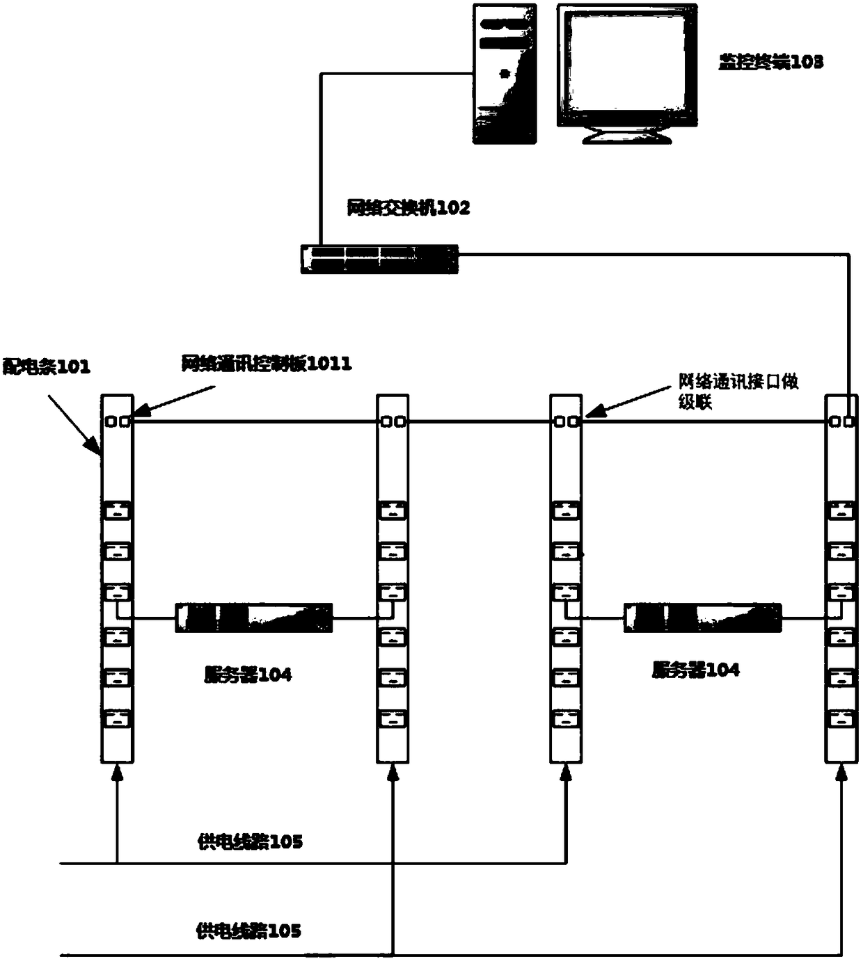
[0083] figure 1 An application scene diagram of distribution bar monitoring according to Embodiment 1 of the present application is shown. It can be seen from the figure that in the application scenario of power distribution bar monitoring in the embodiment of the present application, there are multiple power distribution bars 101, network switches 102, monitoring terminals 103, servers 104 that provide power from connected power distribution bars, and A connected distribution bar provides a plurality of power supply lines 105 for electrical energy. Wherein, the distribution bars are connected in series, and one of the distribution bars is connected to the monitoring terminal 103 through the network switch 102 .
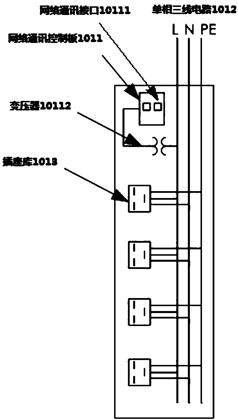
[0084] Currently, common power distribution strips include intelligent rack power distribution strips (Power Distribution Unit, power distribution socket). The smart rack power distribution strip can monitor power parameters such as power supply voltage, current, p...
Embodiment 2
[0101] Figure 4 It shows a flow chart of the steps of a monitoring method for a power distribution bar according to Embodiment 2 of the present application. The power distribution bar is provided with a network communication control board, and the network communication control boards are electrically connected to monitor power distribution. The monitoring platform of the electric energy state is electrically connected with one of the network communication control boards, and the network communication control board is provided with a network communication interface, and the network communication interface supports obtaining standby power from the monitoring platform through active Ethernet, so Said method comprises the steps:
[0102] Step 201, the network communication control board uses the electric energy of the power distribution bar to send the power distribution status information of a plurality of power distribution bars to the monitoring platform.
[0103] The above-m...
Embodiment 3
[0113] Figure 5 It shows a flow chart of the steps of a method for monitoring a power distribution bar according to Embodiment 3 of the present application. The power distribution bar is provided with a network communication control board, and the network communication control boards are electrically connected to monitor power distribution. The monitoring platform of the electric energy state is electrically connected to one of the network communication control boards, and the network communication control board is provided with a network communication interface, and the network communication interface supports obtaining backup power from the monitoring platform through active Ethernet, so Said method comprises the steps:
[0114] Step 301, the network communication control board uses the electric energy of the power distribution bar to send the power distribution status information of a plurality of power distribution bars to the monitoring platform.
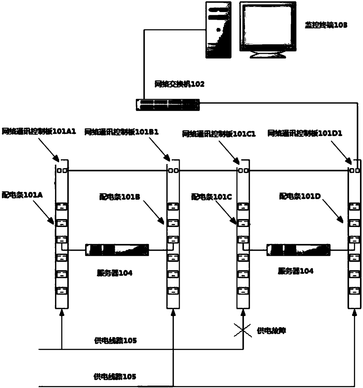
[0115]Step 302 , when...
PUM
 Abstract
Description
Claims
Application Information
 - R&D
- Intellectual Property
- Life Sciences
- Materials
- Tech Scout
- Unparalleled Data Quality
- Higher Quality Content
- 60% Fewer Hallucinations
Browse by: Latest US Patents, China's latest patents, Technical Efficacy Thesaurus, Application Domain, Technology Topic, Popular Technical Reports.
© 2025 PatSnap. All rights reserved.Legal|Privacy policy|Modern Slavery Act Transparency Statement|Sitemap|About US| Contact US: help@patsnap.com


