
Inductive current average detection system and detection method therefor

An inductor current detection system technology, applied in the field of inductor current average value detection system, can solve the problems of low load regulation rate and linear regulation rate, low load regulation rate and linear regulation rate, and inaccurate peak value control, etc., to achieve good Linear regulation and load regulation, the effect of improving linear regulation and load regulation, good linear regulation and load regulation

Active Publication Date: 2018-09-07
QX MICRO DEVICES
View PDF11 Cites 4 Cited by
  • Summary
  • Abstract
  • Description
  • Claims
  • Application Information

AI Technical Summary

Problems solved by technology

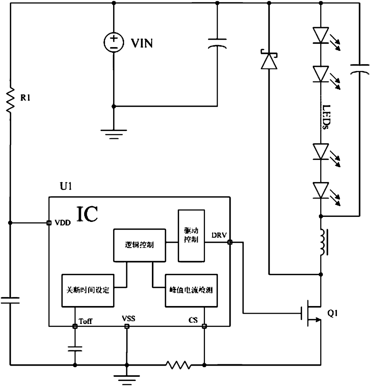
Its inductor peak current can be fixed by the peak current detection circuit, such as figure 1 As shown, but because it is a fixed off-time, so when the input voltage changes, the output voltage does not change in the steady state, according to the volt-second balance principle, the peak current of the inductor does not change, so its output The current does not change; but when the output voltage changes, the peak-to-peak current of the inductor changes linearly when there is no change in the periphery, so the output current also changes accordingly, so the load regulation of the control loop system Low; and for different input voltages, due to the inversion delay of the output logic of the built-in comparator, the peak value control will be inaccurate, so the linear adjustment rate of the control loop system is not high
It can be seen from the above description that for the traditional peak detection control system with fixed off-time, its load regulation rate and linear regulation rate are relatively low, and it cannot effectively detect and control the average current on the inductor.
[0004] The chip of traditional technology controls the peak current of the inductor through the peak current electric measurement, and stabilizes the output current by fixing the off time. The control principle is simple, the stability is good, and it is easy to design. , the output current is a stable value; but when the system input or output changes, the output current changes significantly, and its load regulation and linear regulation are not high, which limits the application of the chip in a wide range of input and output, and cannot meet customer needs.

Method used


Image

  • Inductive current average detection system and detection method therefor
  • Inductive current average detection system and detection method therefor
  • Inductive current average detection system and detection method therefor

Examples


Embodiment Construction

[0044] The present invention will be described in further detail below in conjunction with accompanying drawing:

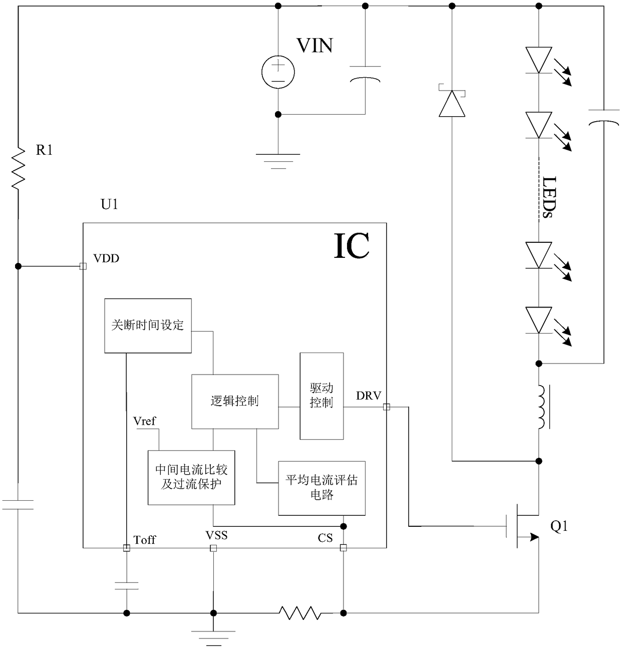
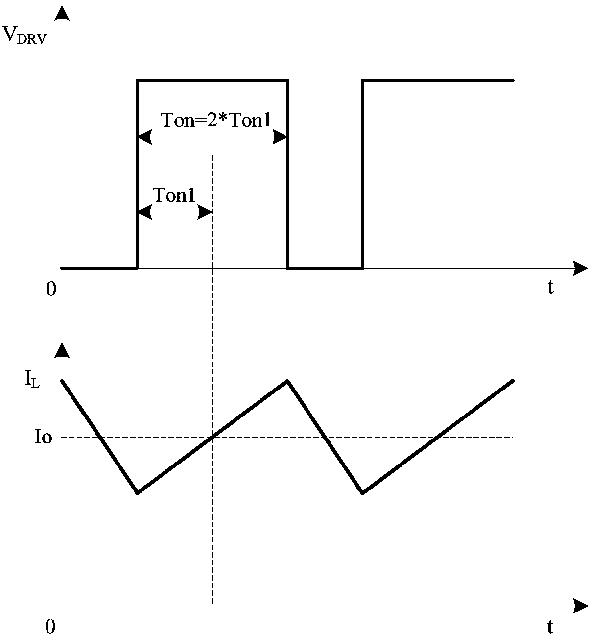
[0045] figure 2 , image 3 A first embodiment of the invention is shown.

[0046] see figure 2 As shown, after the chip starts, control the high-voltage power switch tube Q 1 It is turned on, and the voltage on the CS pin is detected at the same time. At this time, the inductor current gradually rises, and the current passes through the sampling resistor R CS Form the CS pin voltage and enter the intermediate current comparison circuit control module, so when the CS voltage reaches a certain reference voltage, the chip will record the conduction time Ton at this time 1 , and makes the power tube Q 1 Continue to turn on Ton 1 time, so the total on-time Ton=2*Ton 1 ; Afterwards, the chip turns off the high-voltage power switch tube Q 1 , the system enters the freewheeling stage. At this time, the inductor conducts freewheeling through the freewheeling diod...


PUM


Abstract

The invention relates to an inductive current average detection system and a detection method therefor. The inductive current average detection system comprises a main control chip circuit, a power switch tube, a plurality of light-emitting diodes which are connected in series, an inductor and a peripheral circuit, wherein the main control chip circuit is connected with positive electrodes of theplurality of light-emitting diodes which are connected in series through the peripheral circuit; and negative electrodes of the plurality of light-emitting diodes which are connected in series are connected with one end of the inductor and the other end of the inductor is connected with a drain of the power switch tube; and a source plate and a grid of the power switch tube both are connected withthe main control chip circuit.

Description

technical field [0001] The invention relates to an inductance current average value detection system and a detection method for the inductance current average value detection system. Background technique [0002] With the popularization and application of LED driving power, the development of various LED driving chips is also showing a vigorous upward trend. The development of LED drive has experienced constant voltage drive mode, linear constant current drive mode, switching power supply constant current drive mode, and quasi-linear constant current drive mode. Among them, the switching power supply constant current drive mode is the most popular in the market. It has good constant current characteristics, a variety of switching architectures, and good reliability. The low-end switch structure is particularly stable and adjustable, and is popularized and used by designers and customers. [0003] figure 1 Shown is a traditional low-side switch circuit architecture diagram...

Claims


Application Information

Patent Timeline
IPC IPC(8): H05B33/08H05B44/00
CPCH05B45/50H05B45/37Y02B20/30
Inventor 李剑黄朝刚
Owner QX MICRO DEVICES
Learn More