Time-delay stable plasma medium-frequency power supply
An intermediate frequency power supply and plasma technology, applied in the direction of electrical components, electronic switches, high-efficiency power electronic conversion, etc., can solve problems that affect the reliability of equipment systems, affect product failure rates, and complex delay circuits, etc., to improve the power of switching power supplies, Does not affect the delay effect, the effect of small power loss
- Summary
- Abstract
- Description
- Claims
- Application Information
AI Technical Summary
Problems solved by technology
Method used
Image
Examples
Embodiment 1
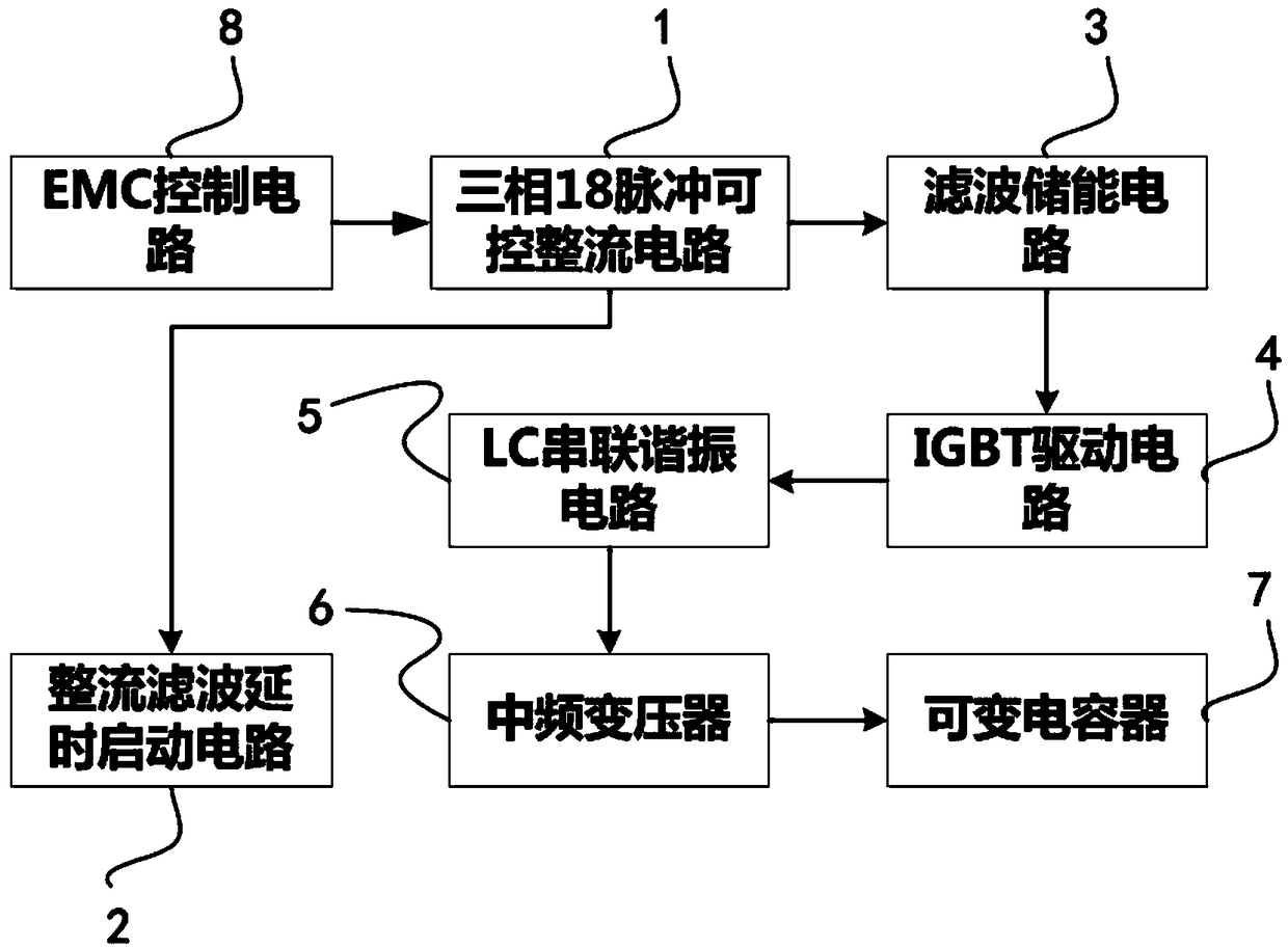
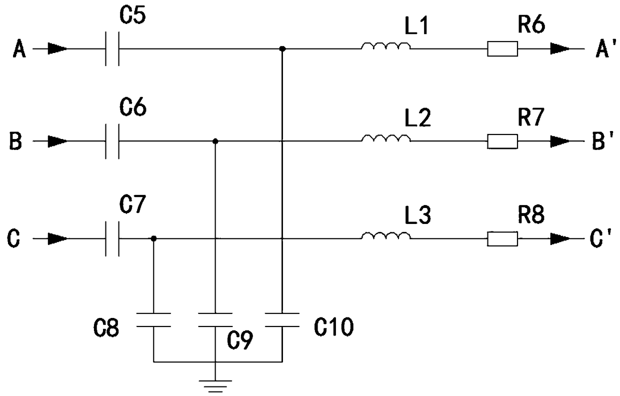
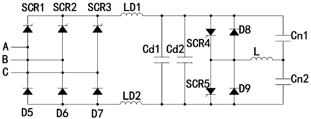
[0028] Such as figure 1 As shown, this embodiment provides a time-delay stable plasma intermediate frequency power supply, including: three-phase 18-pulse controllable rectification circuit 1, rectification and filtering delay start circuit 2, filter energy storage circuit 3, IGBT drive circuit 4, LC A series resonant circuit 5 , an intermediate frequency transformer 6 , a variable capacitor 7 and an EMC management circuit 8 .
[0029] The input terminal of the three-phase 18-pulse controllable rectifier circuit 1 adopts a three-phase AC 380V input, and the first output terminal of the three-phase 18-pulse controllable rectifier circuit 1 is connected to the input terminal of the filter energy storage circuit 3 connected, the second output end of the three-phase 18-pulse controllable rectification circuit 1 is connected to the input end of the rectification filter delay start circuit 2, and the first output end of the filter energy storage circuit 3 is connected to the IGBT T...
Embodiment 2
[0037] Such as Figure 4 As shown, a feedback control circuit 9 is also included, and the feedback control circuit 9 is connected to the filter energy storage circuit 3 through a frequency conversion circuit 10, wherein the input terminal of the frequency conversion circuit 10 is connected to the first filter energy storage circuit 3 The two output terminals are connected, the output terminal of the frequency conversion circuit 10 is connected with the input terminal of the feedback control circuit 9 , and the output terminal of the feedback control circuit 9 is connected with the intermediate frequency transformer 6 .
[0038] The feedback control circuit 9 includes current feedback and voltage feedback, which are used to ensure the stability of the output voltage and output current when the load changes, and use PWM pulse width modulation to maintain the stability of the output voltage.
[0039] Specifically, such as Figure 5 As shown, when the output voltage passes throug...
Embodiment 3
[0041] Such as Figure 6 As shown, the rectification and filtering delay start circuit 2 is composed of triodes Q1, Q2, resistors R1, R2, R3, and R4. Capacitor charging, used to delay the instantaneous increase of current.
[0042] The input end of the rectification filter delay starting circuit 2 is connected in series with the base stage of the triode Q1, and the resistor R1 is connected in series with the diode D5, which is used to protect the circuit to the greatest extent without affecting the delay.
[0043] Specifically, during the delay period, the three-phase AC power supply slowly charges the energy storage capacitor through the resistors R1, R2, R3, and R4. When a pulse signal appears at the access point, Q1 can be turned on instantly. When the pulse signal disappears , C13 can maintain conduction for a certain period of time. During the experiment, the rectification and filtering delay start circuit 2 is connected to 50V 5Hz pulses for many times, and the high lev...
PUM
 Abstract
Description
Claims
Application Information
 - R&D
- Intellectual Property
- Life Sciences
- Materials
- Tech Scout
- Unparalleled Data Quality
- Higher Quality Content
- 60% Fewer Hallucinations
Browse by: Latest US Patents, China's latest patents, Technical Efficacy Thesaurus, Application Domain, Technology Topic, Popular Technical Reports.
© 2025 PatSnap. All rights reserved.Legal|Privacy policy|Modern Slavery Act Transparency Statement|Sitemap|About US| Contact US: help@patsnap.com


