Power output control method for electric bicycle

A technology of power output control and electric bicycles, which is applied to vehicle components, rider driving, transportation and packaging, etc., which can solve the problems of rider inconvenience, failure to provide rider assistance, failure to serve riders, etc. Achieve good riding experience, good riding experience, and improve accuracy

Active Publication Date: 2018-09-11
ANNAIDA DRIVE TECH JIANGSU CO LTD
View PDF5 Cites 2 Cited by
  • Summary
  • Abstract
  • Description
  • Claims
  • Application Information

AI Technical Summary

Problems solved by technology

[0004] The existing electric bicycle power output system is very rough in adjusting the output power of the motor, and cannot provide a specific range of power assistance required by the rider. Therefore, the power assistance provided is often too large or too small for the rider. Inconvenient to come, did not play a role in helping cyclists save effort

Method used


Image

  • Power output control method for electric bicycle
  • Power output control method for electric bicycle
  • Power output control method for electric bicycle

Examples


Embodiment 1

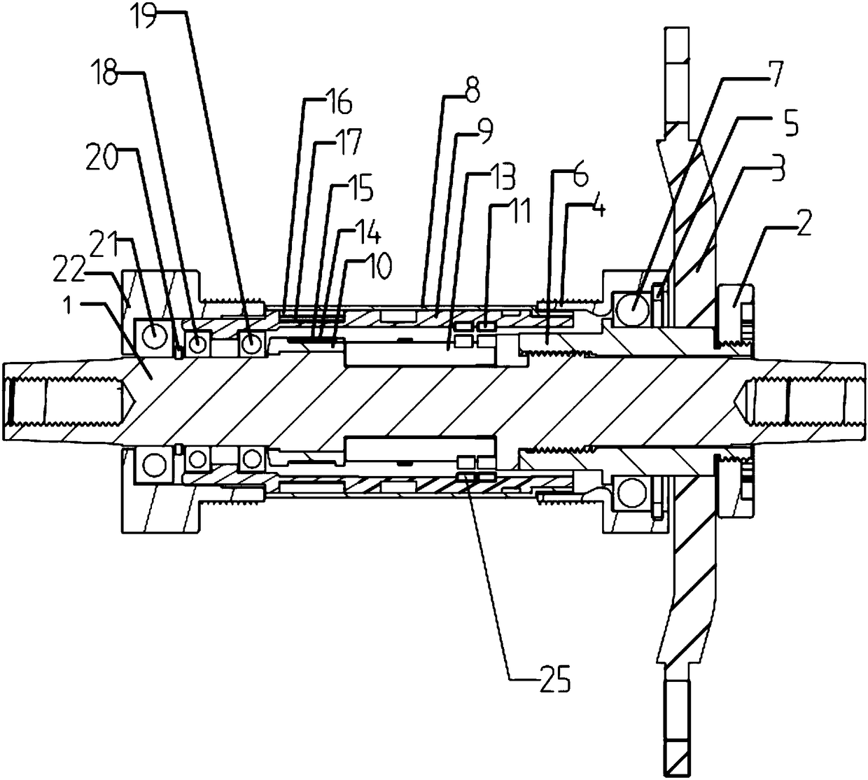
[0053] Embodiment 1 is basically as attached figure 1 As shown: the central shaft 1 torque detection system includes a lock nut 2, a claw 3, a left headset 22, a right headset 4, a central shaft 1, a deformation bridge 6, a sleeve and a magnetic isolation sleeve 10.

[0054] Such as figure 1 As shown in and , the left end and the right end of the central axis 1 are respectively connected to the left crank of the left pedal and the right crank of the right pedal by fastening screws, the left crank is located on the left side of the left headset 22, and the right crank is located on the right headset 4 to the right. An external thread is formed on the outer surface of the central axis 1 at the position connected to the deformation bridge 6 . The deformable bridge 6 is sleeved on the central shaft 1, and the deformable bridge 6 and the central shaft 1 are connected by reverse threads, and the threaded part of the central shaft 1 is locked with the internal thread of the deforma...

Embodiment 2

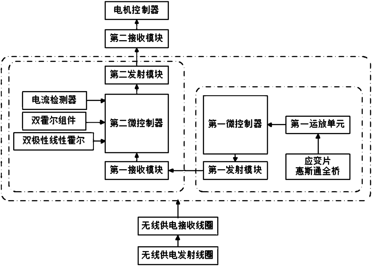
[0108] Such as Figure 6 As shown, the difference between this embodiment and Embodiment 1 is that the double Hall assembly and the bipolar linear Hall 26 are connected in the torque acquisition circuit, and the first micro-controller obtains the characteristic pedaling frequency and the centering frequency from the double Hall assembly. For the electrical signal of the rotation direction of the shaft 1, the first microcontroller obtains the electrical signal representing the crank rotation angle from the bipolar linear Hall 26, and transmits these electrical signals to the torque processing control circuit. At this time, the two circuits can be arranged together on the central axis 1 or separately, the torque acquisition circuit is arranged on the central axis 1 and the torque processing control circuit is arranged on the mounting sleeve 9 . When the torque acquisition circuit and the torque processing control circuit are set separately, the first transmitting module and the ...

Embodiment 3

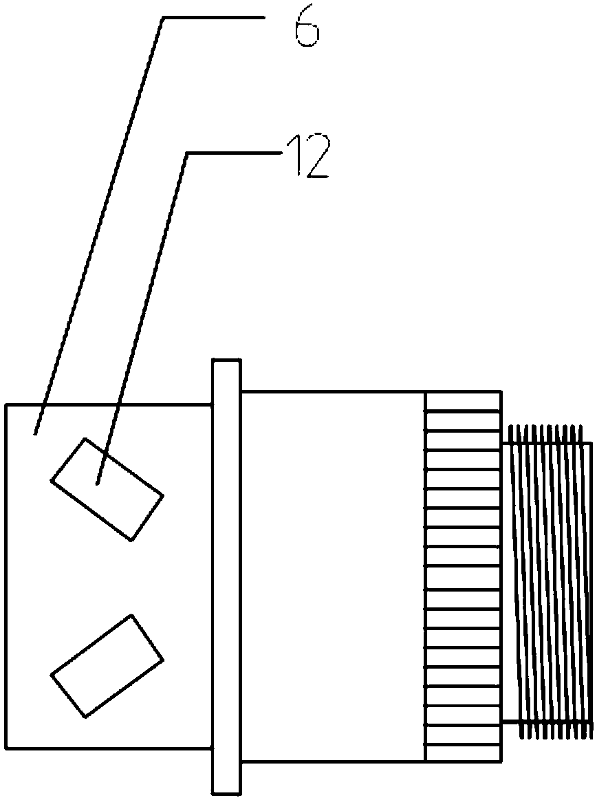
[0110] Such as Figure 7 As shown, the difference between this embodiment and Embodiment 1 is that the double Hall assembly and the strain gauge 12 units are connected in the torque acquisition circuit, and the first micro-controller obtains the characteristic pedaling frequency and the rotation of the central shaft 1 from the double Hall assembly. As for the electrical signal of the direction, the bipolar linear Hall 26 is connected in the torque processing control circuit, and the second micro-controller obtains an electrical signal representing the rotation angle of the crank from the bipolar linear Hall 26. At this time, the two circuits can be arranged together on the central axis 1 or separately, the torque acquisition circuit is arranged on the central axis 1 and the torque processing control circuit is arranged on the mounting sleeve 9 . When the torque acquisition circuit and the torque processing control circuit are set separately, the first transmitting module and t...


PUM


Abstract

The invention relates to the technical field of electric bicycles, and particularly discloses an power output control methodfor an electric bicycle, which comprises the following steps of: detecting atorque signal and a pedaling frequency signal from a central shaft through a manpower driving force detection part and transmitting the torque signal and the pedaling frequency signal to a control part; the control part receives the torque signal and the pedaling frequency signal from the manpower driving force detection part and calculates the manpower output power of the current cyclist to theelectric bicycle according to the torque signal and the pedal frequency signal; the control part automatically selects apower-assisted ratio according to the pedaling frequency signal, and calculatesthe theoretical output power of the motor through the manpower output power and the power-assisted ratio; the control part controls the motor to rotate according to the theoretical output power of themotor. The method can provide accurate power-assisted output.

Description

technical field [0001] The invention relates to the technical field of electric bicycles, in particular to an electric bicycle power output control method. Background technique [0002] An electric bicycle is a kind of power-assisted bicycle. It is a riding tool between a bicycle and an electric vehicle. It uses electric power to assist manpower to provide the kinetic energy needed for the bicycle to travel. It is people's pursuit of high efficiency, convenience, health, and The product of an environmentally friendly lifestyle. [0003] In order to enable the electric bicycle to provide assistance to the rider more appropriately, a power output control system for controlling the output power of the motor will be installed on the electric bicycle. The existing electric bicycle power output control system generally includes a human driving force detection unit and The control part starts the power output control system of the electric bicycle through a switch or other existin...

Claims


Application Information

Patent Timeline
Patent Type & Authority Applications(China)
IPC IPC(8): B62M6/45
CPCB62M6/45
Inventor 夏静满胡江勇李家成
Owner ANNAIDA DRIVE TECH JIANGSU CO LTD
Why Eureka
Try Eureka