Generation method, apparatus and terminal of disparity map

A disparity map and difference map technology, applied in image enhancement, image analysis, image data processing, etc., can solve the problems of wasting computing resources, reducing the efficiency of stereo matching algorithms, etc., and achieve the effect of improving efficiency

Active Publication Date: 2018-09-11
HISENSE
View PDF8 Cites 20 Cited by
  • Summary
  • Abstract
  • Description
  • Claims
  • Application Information

AI Technical Summary

Problems solved by technology

[0005] In order to solve the problem of disparity estimation for some meaningless pixels in the existing stereo matching algorithm, which leads to a waste of computing resources and reduces the efficiency of the stereo matching algorithm, this application provides a method, device and terminal for generating a disparity map. Realize targeted disparity estimation for those pixels that are meaningful for obstacle detection, effectively use computing resources, improve the efficiency of stereo matching algorithms, and further improve the efficiency of subsequent obstacle detection based on disparity maps

Method used


Image

  • Generation method, apparatus and terminal of disparity map
  • Generation method, apparatus and terminal of disparity map
  • Generation method, apparatus and terminal of disparity map

Examples


Embodiment 1

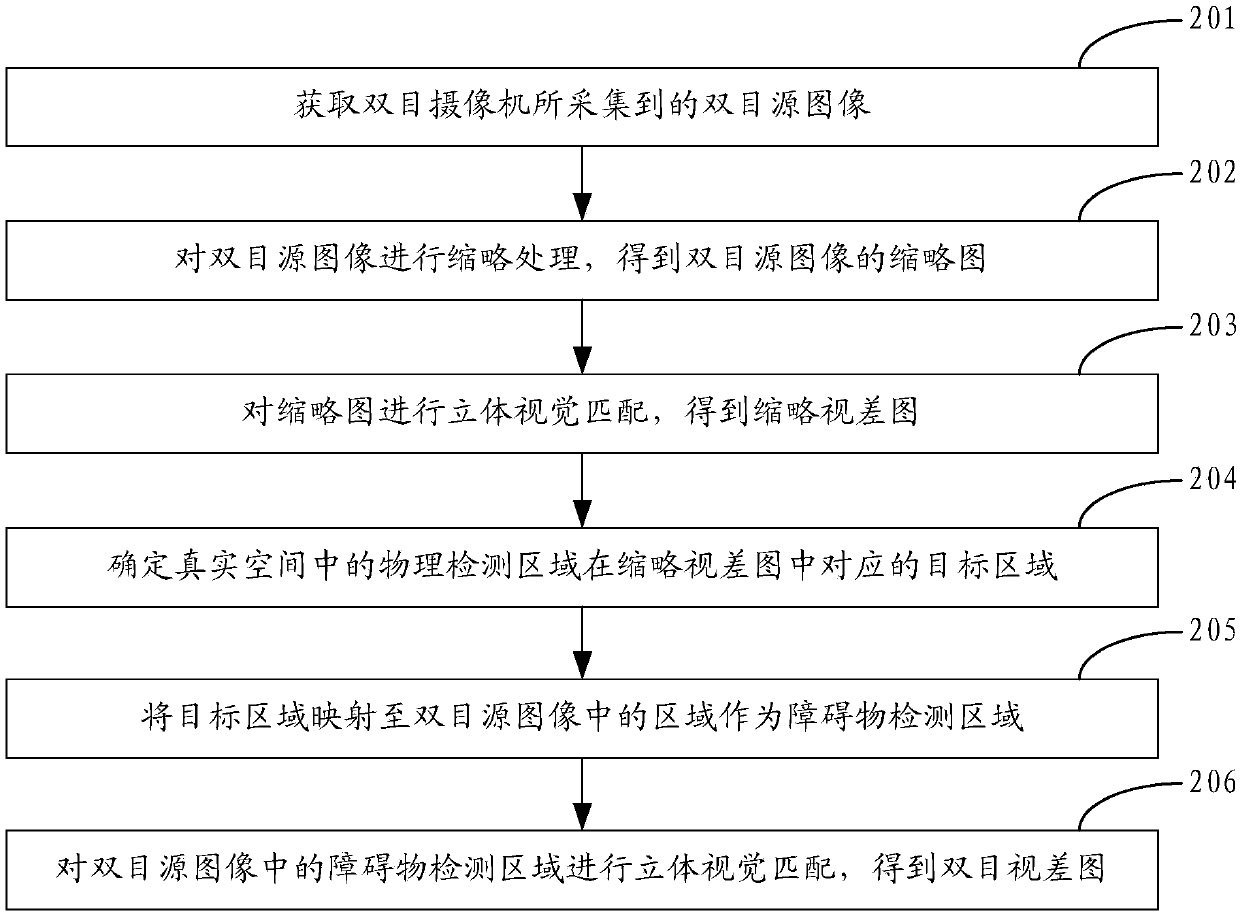
[0078] See figure 2 , is a flow chart of an embodiment of a method for generating a disparity map provided in an exemplary embodiment of the present application, and the method may include the following steps:

[0079] Step 201: Obtain a binocular source image captured by a binocular camera.

[0080] Those skilled in the art can understand that, in order to realize the method for generating the disparity map provided by the embodiment of the present application, a binocular camera can be arranged on the vehicle. The binocular camera has two cameras on the left and right. During an image acquisition process, the The left and right cameras capture an image respectively. For the convenience of description, in the embodiment of the present application, the two images captured by the two cameras of the binocular camera are collectively referred to as binocular source images.

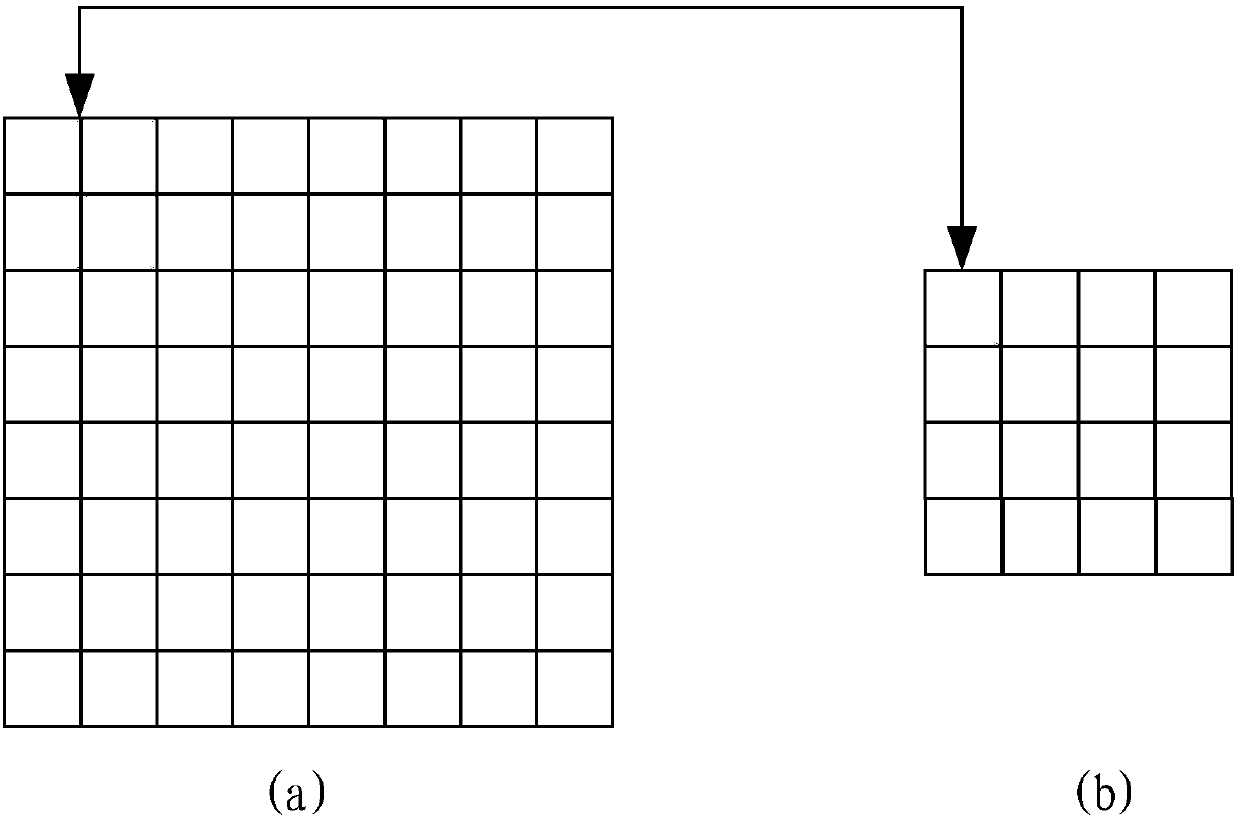
[0081] Step 202: Perform thumbnail processing on the binocular source image to obtain a thumbnail of the...

Embodiment 2

[0096] See Figure 4 , is a flow chart of another embodiment of a method for generating a disparity map provided in an exemplary embodiment of the present application, and the method may include the following steps:

[0097] Step 401: Calculate the X-axis coordinates and Y-axis coordinates of the disparity points in the thumbnail disparity map in the preset three-dimensional coordinate system.

[0098] In the embodiment of the present application, the horizontal midpoint between the two imaging planes in the binocular camera can be used as the origin, the positive direction of the Z-axis is pointed parallel to the ground and directly in front of the front of the vehicle, and the Y-axis is perpendicular to the ground and pointed below the ground Positive direction, pointing to the right side of the driver parallel to the ground as the positive direction of the X-axis, establish a three-dimensional coordinate system, such as Figure 5 Shown is an example of a three-dimensional co...


PUM


Abstract

The application provides a generation method, apparatus and terminal of a disparity map, and relates to the technical field of auxiliary driving. The method includes: obtaining a binocular source image acquired by a binocular camera; performing abbreviation processing on the binocular source image to obtain a thumbnail of the binocular source image; performing stereo vision matching on the thumbnail to obtain a thumbnail disparity map; determining a target area corresponding to a physical detection area in the thumbnail disparity map in a real space; mapping the target area to an area in the binocular source image as an obstacle detection area; and performing stereo vision matching on the obstacle detection area in the binocular source image to obtain a binocular disparity map. By adoptingthe method, disparity estimation of pixel points having significance for obstacle detection can be performed in a targeted manner, calculating resources can be effectively utilized, the efficiency ofa stereo matching algorithm is improved, and the efficiency for subsequent obstacle detection based on the disparity map is further improved.

Description

technical field [0001] The present application relates to the technical field of driving assistance, and in particular to a method, device and terminal for generating a disparity map. Background technique [0002] In recent years, the obstacle detection method based on binocular stereo vision (Binocular Stereo Vision) technology has become a research hotspot in the field of automotive assisted driving. In related technologies, stereo vision matching algorithms can be divided into two categories according to the different primitives used. One is a global-based stereo matching algorithm, and the other is a feature-based stereo matching algorithm. [0003] Among them, the global-based stereo matching algorithm means that the disparity estimation is performed for each pixel in the source image. Therefore, in the disparity map obtained by the global-based stereo matching algorithm, there is an effective disparity at each pixel. Difference, based on this, the disparity map obtain...

Claims


Application Information

Patent Timeline
Patent Type & Authority Applications(China)
IPC IPC(8): G06T7/55G06T7/33
CPCG06T7/337G06T7/55G06T2207/10028G06T2207/20228
Inventor 赵启东
Owner HISENSE
Why Eureka
Try Eureka