Method, device and computer-readable storage medium for relay transmission

A technology for transmitting resources and configuring information, which is applied in the field of communication, can solve problems such as high complexity and large data processing delay, and achieve the effect of reducing transmission delay, reducing processing complexity, and improving overall system performance

Active Publication Date: 2021-06-29
GUANGDONG OPPO MOBILE TELECOMM CORP LTD
6 Cites 0 Cited by

AI-Extracted Technical Summary

Problems solved by technology

[0004] In the prior art, the D2D relay relays the data transmission between the D2D terminal and the network device through the Internet Protocol (Internet Protocol, IP) layer (that is, layer 3), and the received data packets need to pass through layer 1 (that is, the physical layer), layer 2 (including Media Access Control (...

Method used

[0108] Optionally, the first Layer 2 PDU may carry identification information of the remote terminal device, the identification information of the remote terminal device is used to identify the remote terminal device, and the identification information of the remote terminal device may be To be identified by the relay terminal device, for example, the relay terminal device can identify the identification information of the remote terminal device through Layer 2, but this embodiment of the present invention is not limited thereto. Optionally, the identification information of the remote terminal device may include a terminal device identifier of the remote terminal device, and the terminal device identifier may be used to uniquely identify the remote terminal device. Wherein, the terminal device identifier may be predefined. For example, the terminal device identifier may specifically be the device identifier of the remote terminal device or the user identifier of the remote terminal device, and so on. Optionally, the identification information of the remote terminal device may also include a specific identifier of the remote terminal device, and the specific identifier of the remote terminal device is used to uniquely identify the remote terminal device in relay transmission. The specific identifier may be predefined or...

Abstract

The invention discloses a method and device for relay transmission, which can reduce the complexity and time delay of data processing. The method includes: a relay terminal device receives the first layer-2 PDU sent by a sender device to a receiver device, wherein, The first Layer 2 PDU carries the identification information of the remote terminal equipment, or the first Layer 2 PDU is scheduled through the PDCCH scrambled by using the RNTI of the remote terminal equipment; the relay terminal equipment according to the first two Layer PDU, generating a second Layer 2 PDU; the relay terminal device sends the second Layer 2 PDU to the receiving end device; wherein, the sending end device is the remote terminal device and the receiving end device is a network device, or The sending end device is a network device and the receiving end device is the remote terminal device.

Application Domain

Technology Topic

Image

  • Method, device and computer-readable storage medium for relay transmission
  • Method, device and computer-readable storage medium for relay transmission
  • Method, device and computer-readable storage medium for relay transmission

Examples

  • Experimental program(1)

Example Embodiment

[0093]Next, the technical solutions in the embodiments of the present invention will be described in contemplation in the embodiments of the present invention, which will be described, and it is understood that the described embodiments are intended to be in an embodiment of the present invention, not all of the embodiments. Based on the embodiments in the present invention, all other embodiments obtained without making creative labor without making creative labor, and should belong to the scope of the present invention.
[0094] It will be appreciated that the term "system" and "network" herein are often used interchangeably herein. The term "and / or" herein is merely a relationship of the associated object, indicating that there are three relationships, such as A and / or B, which may be represented: Alone A, while there is A and B, alone B These three situations. In addition, the characters "/" in this article generally indicate that the front and rear association objects are a "or" relationship.
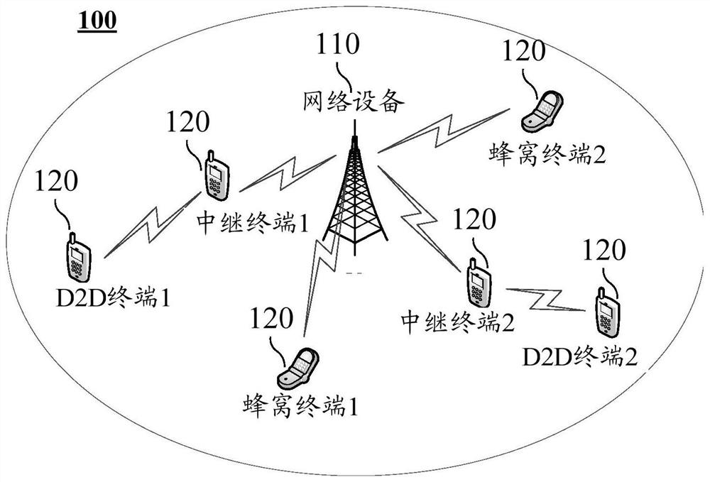
[0095] figure 1 It is a schematic diagram of a wireless communication system 100 according to an embodiment of the present invention, and the wireless communication system 100 includes at least one network device 110. Network device 100 can be a device that communicates with a terminal device. Each network device 100 can provide communication coverage for a particular geographic area, and can communicate with a terminal device located within the coverage area. The network device 100 can be a base station (NODEB, NB) in the Code Division Multiple Access (CDMA) system, or a base station in the WCDMA system, or Evolutionary Node B, ENODEB, or Wireless Controller in Cloud Radio Access Network (CRAN), or the network device can be a relay station, an access point, Inboard equipment, wearable devices, network devices in the future 5G network or future evolved public land mobile network (PUBLIC LAND Mobile NetWork, PLMN).
[0096] The wireless communication system 100 also includes a plurality of terminal devices 120 located within the coverage of network device 110. The terminal device 120 can be moving or fixed. The terminal device 120 can refer to access terminal, user equipment (UE), user unit, subscriber station, mobile station, mobile station, remote station, remote terminal, mobile device, user terminal, terminal, wireless communication device, user agent Or user equipment. The access terminal can be a cellular telephone, a cordless telephone, a session initiation, a WiReless Localoop, WLL station, a personal digital processing (PDA), wireless communication Handheld devices, computing devices, or other processing devices connected to wireless modems, in-vehicle devices, wearable devices, terminal devices in future 5G networks or terminal devices in future evolved PLMNs, and the like.
[0097] figure 1 A network device and six terminal devices are exemplary, optionally, the wireless communication system 100 can include a plurality of network devices and can include other numbers of terminal devices within the coverage of each network device. Examples do not limit this. In addition, the wireless communication system 100 can also include other network entities such as mobile management entities, a service gateway, S-GW, a Packet Data Network Gateway (P-GW), but The embodiment of the present invention is not limited thereto.
[0098] Specifically, the terminal device 120 can communicate in a cellular communication mode or D2D communication mode, wherein in the cellular communication mode, the terminal device can communicate with other terminal devices through the network device; in the D2D communication mode, the terminal device can pass the D2D chain. The road is directly communicated with other terminal devices.
[0099] in figure 1 In a plurality of terminal devices 120, including a honeycomb terminal device, a D2D terminal device, and a relay terminal device, wherein the cellular terminal device communicates with the network device 110 with a cellular communication technology. The D2D terminal device implements data transmission between the network device through the relay terminal device, wherein the relay terminal device has a PC5 interface between the relay terminal device and the D2D terminal device, which communicates with D2D communication technology, wherein the D2D communication technology can be specifically The bypass (SL) technology in the LTE, or WiFi or Bluetooth technology, or other D2D communication technology, the embodiment of the present invention is not limited. There is a UU interface between the relay terminal device and the network device, which communicates with cellular communication technology.
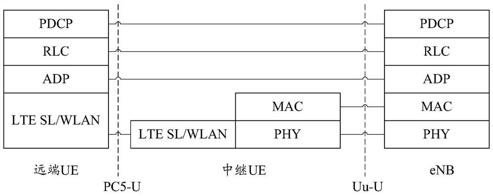
[0100] In the prior art, the relay terminal device is relayed by a layer trunk manner, and the data processing is delayed. In the embodiment of the present invention, the relay terminal device can use the data transmission between the network device and the D2D terminal device, at this time, at this time, a two-layer PDU can be used in the UU interface and the PC5 interface. Mac PDU, RLC PDU or PDCPDU is relayed. Figure 2A and Figure 2B The user plane protocol stack examples of each device are shown schematically, whereby, optionally, the user plane protocol stack of the relay terminal device may include a user plane of layer one and layer two, D2D terminal devices. The protocol stack can include layer 1, layer two, and layer three, the user plane protocol stack of the network device can include layer 1, layer two and layer three, where the layer of the relay terminal device is respectively associated with the D2D terminal device And the layer of the network device is a peer layer, the layer two of the relay terminal device respectively corresponds to the layer two of the D2D terminal device and the layer two of the network device. At this time, the D2D terminal device, the relay terminal device, and the network device can be relayed in a second-layer PDU.
[0101] At this time, it is optionally, the user plane protocol stack of the relay terminal device may include only layer one and layer two, and does not include layer three. Alternatively, the layer 2 of the relay terminal device can be used to identify the remote terminal device of the relay transmission. For example, the layer 2 of the relay terminal device can be used to identify and encapsulate the identification information of the D2D terminal device, but the embodiment of the present invention is not limited.
[0102] Specifically, in Figure 2A The user plane protocol stack of the D2D terminal device and the network device may include a layer (i.e., a Physics, a PHY layer), a layer 2, and a higher layer, wherein the layer two includes a MAC layer, an RLC layer, and a PDCP layer. The user plane protocol stack of the relay terminal device may include only layer one and layer two, wherein the layer 2 may include only the MAC layer, or only the MAC layer and the RLC layer, or include the MAC layer, the RLC layer, and the PDCP layer. At this time, the data relay transmission between the D2D terminal device, the relay terminal device, and the network device can realize the relay transmission by identifying the identification information of the D2D terminal device, wherein the identification information of the D2D terminal device can be Layer 2 implementation, but the embodiment of the present invention is not limited.
[0103] As another alternative embodiment, Figure 2B In the middle, the D2D terminal equipment and the layer two pairs of network devices have added adaptation layers. At this time, the protocol stack of the D2D terminal device can include a PDCP layer, an RLC layer, an adapTive, an ADP layer, and a more layer corresponding to the D2D communication technology employed with the PC5 interface, wherein if the D2D communication technology is specifically For the bypass technology of LTE, the more layer can be specifically a MAC layer and a PHY layer, and if the D2D communication technology is other communication technologies, for example, Bluetooth or WiFi technology, etc., the lower layer can be This other communication technology corresponds to the layer corresponding to the MAC layer and the physical layer. The relay protocol stack of the relay terminal device can include a layer one and a layer two corresponding to the D2D communication technique. The relay protocol stack of the network device can include a PDCP layer, an RLC layer, an ADP layer, a MAC layer, and a PHY layer. For convenience of understanding, the following examples are described as an example of the MAC layer and the physical layer, but the embodiment of the present invention is not limited thereto.
[0104] Alternatively, the adaptation layer can be located between the MAC layer and the RLC layer, or between the RLC layer and the PDCP, and the embodiment of the present invention is not limited. In the embodiment of the present invention, the adaptation layer can be used to identify identification information of the D2D terminal device, or optionally can also be used to identify relay specific LCIDs for indicating relay transmission. Further, it is optionally, the adaptation layer can be used to convert data transmitted from the lower layer into a communication technique independent in the form of communication techniques, and optionally to transmit the processed data to the upper layer for further deal with. Alternatively, the adaptation layer can carry a layer two identifier of the D2D terminal device, or further carrying a relay specific logic channel identifier, wherein the relay specific logic channel identifier can be used to identify relay data. At this time, optionally, the second layer PDU transmitted by the relay terminal device to the network device to the network device may not carry any information of the D2D terminal device, and the relay data is identified by the relay specific logic channel identifier, but the present invention implements Example is not limited thereto.
[0105] image 3 A method 200 of a relay transmission provided by an embodiment of the present invention is shown schematically. The method 200 can be applied to the wireless communication system 100 described above, but the embodiment of the present invention is not limited thereto. Specifically, the method 200 can be applied to the relay transmission of uplink data, that is, the remote terminal device transmits uplink data to the network device through the relay terminal device. At this time, the transmitting end device is specifically a remote terminal device (also known as D2D terminal device), the receiving device is specifically a network device. Alternatively, the method 200 can also be applied to the relay transmission of downlink data, that is, the network device transmits downlink data to the remote terminal device through the relay terminal device. At this time, the transmitting device is a network device, and the receiving end device is far. End of terminal devices, but embodiments of the present invention are not limited.
[0106] S210, the transmitting device is to send data or to be transmitted to encapsulate processing, generating the first two-layer protocol data unit (PROTOCOL DATA Unit, PDU).
[0107] It should be understood that in the embodiment of the present invention, the second layer PDU can refer to the outermost layer or the highest layer of the data to be packaged in the layer 2 of the device. Alternatively, layer 2 can include a MAC layer, an RLC layer, and a PDCP layer, and the second layer PDU can specifically refer to the MAC PDU, RLC PDU, or PDCP PDU. Alternatively, if the layer two of the remote terminal device and the network device also includes an adapter layer, the specific form of the second layer PDU transmitted in the PC5 interface can correspond to the D2D communication technology employed by the PC5 interface. For example, if the D2D communication technology is the bypass technology of the LTE, the second layer PDU transmitted by the PC5 interface can be specifically MACPDU, and if the D2D communication technology is Bluetooth or WiFi technology, the second layer PDU transmitted by the PC5 interface can The second layer PDU corresponding to the MAC PDU in Bluetooth or WiFi technology is not limited thereto.
[0108]Alternatively, the first two-layer PDU can carry identification information of the distal terminal device, the identification information of the remote terminal device, is used to identify the remote terminal device, and the identification information of the remote terminal device can be The end device recognition, for example, the relay terminal device can identify the identification information of the remote terminal device through the layer two, but the embodiment of the present invention is not limited thereto. Alternatively, the identification information of the far end device can include a terminal device identifier of the remote terminal device, which can be used to uniquely identify the remote terminal device. Wherein, the terminal device identifier can be predefined. For example, the terminal device identifies can specifically specifically, a device identifier of the remote terminal device or a user ID of the remote terminal device, and the like. Alternatively, the identification information of the remote terminal device may also include a particular identifier of the remote terminal device, and a particular identifier of the remote terminal device is for uniquely identifying the remote terminal device in the relay transmission. This particular identification can be predefined or a network device configuration. The length of the particular identification can be less than the length of the terminal device identifier to reduce signaling overhead. For example, the particular identifier may be a layer two identifier, i.e., an identifier of the package and parsing in the layer of the device, wherein the layer two identifier may be predefined, or the network device is allocated by the remote terminal device, for example The layer 2 identification is assigned by the network device in the process of establishing a bearer for the remote terminal device, but the embodiment of the present invention is not limited thereto. Alternatively, the layer two identifier can be placed at the PDCP layer, the RLC layer, or the MAC layer, i.e., by the PDCP layer, the RLC layer or MAC layer package and parsing. Alternatively, if the distal terminal device and the layer 2 of the network device also include a separate adaptation layer, the layer two identifier can be disposed at the corresponding layer of the adaptation layer or D2D communication technology, for example, if the relay terminal device The PC5 interface between the distal terminal devices uses bypass techniques, then the layer two identifier can be set in the MAC layer, but the embodiment of the present invention is not limited.
[0109] If the remote terminal device and the network device have a separate adaptation layer, the package and resolution of the identification information of the remote terminal device are performed by the adapter layer, and when the remote terminal device or network device is required to send, The PDCP layer, the RLC layer, and the adaptive layer package are sequentially filled. Among them, identification information (e.g., layer II identification) of the remote terminal device can be carried in the adapter layer, but the embodiment of the present invention is not limited thereto. Alternatively, if the remote terminal device and the network device do not have a separate adaptation layer, the resolution and encapsulation of the identification information of the remote terminal device is performed by the MAC layer, then the remote terminal device or network device is required to send When, for example, the network device receives data from the remote terminal device from the network side, the PDCP layer, the RLC layer, and the MAC layer package may be sequentially paid in order, wherein the identification information of the remote terminal device can be carried in the MAC layer (eg, Layer 2 identification), but the embodiment of the present invention is not limited thereto.
[0110] S220, the transmitting device transmits the first two-layer PDU to the relay terminal device.
[0111] Alternatively, the first two-layer PDU may include a logical channel identifier, a LCID. The logical channel identification field or the setting of the bearer identity field can make the relay terminal device determine the first two. The data or information carried by the layer PDU needs to be forwarded, ie the data carried in the second two-layer PDU is relay data. For example, the bearer identification field can be used to carry the bearer identifier corresponding to the remote terminal device, which can be used to carry a relay specific LCID to indicate the data of the first two-layer PDU as relay data. The relay terminal device is required for forwarding, wherein the relay, a particular LCID may be preconfigured, or a network device allocation, such as the network device allocates the relay-specific LCID in the process of establishing a bearer for the remote terminal device. However, the embodiment of the present invention is not limited thereto.
[0112] Alternatively, if the sender device is a remote terminal device and the receiving device is a network device, the remote terminal device can transmit the first two to the relay terminal device by a transmission resource for relay transmission. Layer PDU. At this time, the relay terminal device can determine the data carried in the first two-layer PDU to be forwarded according to the transmission resource occupied by the first two-layer PDU, but the embodiment of the present invention is not limited thereto.
[0113] Alternatively, the relay terminal device can also determine the data carried by the first two-layer PDU as relay data by other means, and the embodiment of the present invention is not limited.
[0114] Alternatively, the relay terminal device can forward data carried by the first two-layer PDU based on the identification information or RNTI of the remote terminal device. Specifically, the receiving end device can encapsulate the data carried in the first two-layer PDU, such as package processing of data carried by the first two-layer PDU, obtaining the second two-layer PDU, and The second two-layer PDU is transmitted to the receiving device, but the embodiment of the present invention is not limited thereto.
[0115] S230, the relay terminal device receives the first two-layer PDU transmitted by the transmitting device, determines the distal terminal device corresponding to the first two-layer PDU, and packages the data carried in the first two-layer PDU to generate the first Two-layer PDU.
[0116] Alternatively, the relay terminal device determines the distal terminal device corresponding to the first two-layer PDU according to the identification information of the distal terminal device carried by the first two-layer PDU, for example, the relay terminal device The identification information carried in the first two-layer PDU can be identified in the layer 2 to determine the distal terminal device corresponding to the first two-layer PDU. Alternatively, when the transmitting device is a network device, it is optionally, the data carried in the first two-layer PDU is a network device scheduling by a Physical Downlink Control Channel, a PDCCH. The remote terminal device is scrambled by radio network temporary identity (RNTI), RADIO NETWORK TEMPORY IDENTIN. At this time, the relay terminal apparatus can determine the remote terminal device corresponding to the first two-layer PDU according to the RNTI used to schedule the PDCCH of the first two-layer PDU, but the embodiment of the present invention is not limited thereto.
[0117] Alternatively, the RNTI of the remote terminal device can be a predefined, or the network device is allocated by the remote terminal device, for example, the network device is the far end in the process of establishing a bearer for the remote terminal device. Terminal devices allocate RNTI. At this time, the relay terminal device can determine the remote terminal device corresponding to the first two-layer PDU according to the RNTI used to schedule the PDCCH of the first two-layer PDU, but the embodiment of the present invention is not limited thereto. .
[0118] Alternatively, the relay terminal device can encapsulate the data carried by the first two-layer PDU, generate a second two-layer PDU, for example, to encapsulate data carried in the first two-layer PDU in the layer 2 Processing, generating second two-layer PDU. Wherein, the first two-layer PDU can satisfy the interface communication protocol between the relay terminal device and the transmitting end device, the second two-layer PDU can satisfy the interface communication protocol between the relay terminal device and the receiving device.
[0119] Specifically, if the distal terminal device and the network device do not include a separate adaptation layer, the relay terminal device can perform unscaping and package processing on the first two-layer PDU to process the MAC of the first interface. The PDU is converted to the MAC PDU of the second interface, where the first interface is the communication interface between the relay terminal device and the transmitting device, which is a communication interface between the relay terminal device and the receiving device. . For example, if the transmitting device is a remote terminal device and the receiving device is a network device, the first interface is a PC5 interface, the second interface being a UU interface. If the sender device is a network device and the receiving device is a remote terminal device, the first interface is a UU interface, the second interface is a PC5 interface. For example, if the transmitting device is a network device, when the relay terminal device determines that the data carried by the first two-layer PDU is relay data, the data can be packaged according to the communication technology of the PC5 interface, and the PC5 is satisfied. The second two-layer PDU of the interface protocol, and transmits it over the user plane of the PC5 interface (PC5-User Plane, PC5-U). For example again, if the transmitting end device is a remote terminal device, when the relay terminal device determines that the data carried in the first two-layer PDU is relay data, the data can be packaged according to the communication technology of the UU interface, A second two-layer PDU (e.g., LTE UU MAC PDU) satisfying the UU interface protocol.
[0120] Alternatively, the second two-layer PDU can carry identification information of the remote terminal device, such as a terminal device identifier or a layer ID.
[0121] Specifically, if the transmitting device is a remote terminal device and the receiving end device is a network device, it is optionally, the first two-layer PDU can carry the terminal device identifier of the remote terminal device, at this time, the relay terminal The device can determine the corresponding layer two identifier corresponding to the terminal device, and carry this layer two identity in the second two-layer PDU. The network device can determine the remote terminal device corresponding to the second two-layer PDU, and to the core network device (e.g., packet data network gateway) based on the layer ID of the distal terminal device carried in the second two-layer PDU. (PACKET DATA NETWORK GATEWAY, P-GW)) Sends data carried in the second two-layer PDU.
[0122] Alternatively, before the relay terminal device transmits the second two-layer PDU to the network device, the relay terminal device can also initiate an uplink authorization request process, and transmitted to the network device using the uplink transmission resource allocated by the network device. The second layer of PDU. Among them, as an alternative embodiment, the relay terminal device can perform the uplink authorization request flow initiated when the relay terminal device needs to send uplink data to the network device, for example, the relay terminal device sends a scheduling request to the network device. The scheduling request is used to request network devices to assign up to transfer resources for the relay terminal device; the network device can assign a UNDTP to the relay terminal device, and transmit an uplink authorization to the relay terminal device. Upstream authorization is used to indicate the transmission resource allocated by the network device for the relay terminal device; the relay terminal device can transmit the second two-layer PDU to the network device using the uplink transmission resource.
[0123] As another alternative embodiment, the relay terminal device can determine the preamble allocated by the remote terminal device, and initiate an uplink authorization request process by transmitting the preamble to the network device. At this time, the network device can determine the remote terminal device corresponding to the received uplink transmission resource, and after receiving the second two-layer PDU, according to the second two-layer PDU Upstream transmission resource determines the remote terminal device. At this time, the second two-layer PDU may not carry the identification information of the remote terminal device, so that the signaling overhead can be further saved.
[0124] As another alternative embodiment, the relay terminal device can transmit a buffer status Report, BSR to the network device, wherein the BSR carries identification information of the remote terminal device, such as a layer two identification or The terminal device identifier, after receiving the BSR, the identification information of the remote terminal device can be identified, and transmit a PDCCH to the relay terminal device to schedule uplink data transmission of the remote terminal device, wherein the PDCCH carries identification information of the remote terminal device. The relay terminal device can transmit the second two-layer PDU to the network device according to the PDCCH after receiving the PDCCH. The network device can determine a terminal device corresponding to the second two-layer PDU according to a PDCCH for scheduling the second two-layer PDU. At this time, optionally, the second two-layer PDU transmitted by the relay terminal device. The identification information of the remote terminal device may not be carried, but the embodiment of the present invention is not limited thereto.
[0125]If the sender device is a network device and the receiving end device is a remote terminal device, it is optionally, the first two-layer PDU can carry the layer two identity of the remote terminal device. At this time, the relay terminal device can determine the terminal device identifier corresponding to the layer two identification, and carrying the terminal device identifier in the second two-layer PDU. When the remote terminal device receives the second two-layer PDU, it is possible to determine if the second two-layer PDU is transmitted to himself according to the terminal device of the second two-layer PDU. At this time, the data relay transmission between the distal terminal device and the relay terminal device can identify the remote terminal device through the terminal device identifier of the remote terminal device, and the relay terminal device and the network device The data relay transmission can identify the remote terminal device by the layer two identity of the remote terminal device, and therefore, the remote terminal device may not know the layer two identifier itself, but the embodiment of the present invention is not limited to this.
[0126] Alternatively, the second two-layer PDU can also carry an instruction information for indicating data of the second two-layer PDU carries as relay data, for example, if the network device includes an adaptation layer, the indication information can include Relay specific LCID. At this time, the network device can determine whether the received second two-layer PDU received is relayed by a relay terminal device according to the indication information, but the embodiment of the present invention is not limited thereto.
[0127] Alternatively, the second two-layer PDU can also carry identification information of the relay terminal device, such as a terminal device identification, and the like, but the embodiment of the present invention is not limited thereto.
[0128] S240, the relay terminal device transmits the second two-layer PDU to the receiving device.
[0129] The relay terminal device can forward data carried by the first two-layer PDU according to the distal terminal device corresponding to the first two-layer PDU, for example, the relay terminal device transmits the receiving device device The second two-layer PDU carries the identification information of the distal terminal device, or the second two-layer PDU is transmitted by the uplink transmission resource assigned by the network device for the remote terminal device, but the embodiment of the present invention is not limited thereto. .
[0130] Alternatively, if the receiving device is a remote terminal device, the relay terminal device can transmit the second two-layer PDU to the remote terminal device using a transmission resource for relay transmission, the remote terminal device According to the transmission resource occupied by the second two-layer PDU, it is determined that the second two-layer PDU carries relay data is forwarded by the relay terminal device, but the embodiment of the present invention is not limited thereto.
[0131] After receiving the second two-layer PDU, the receiving device can perform parsing the second two-layer PDU. For example, if the receiving device is a network device and the second two-layer PDU carries a relay specific logic channel identifier, the network device can be identified by a relay specific logical channel identifier carried in the second two-layer PDU to determine the first The data carried by the second two-layer PDU is relay data. Alternatively, the network device can transmit data carried by the second two-layer PDU to the core network through the S1-U interface. Alternatively, the network device can also determine the remote terminal device corresponding to the second two-layer PDU according to the identification information of the distal terminal device carried in the second two-layer PDU. At this time, if the network device and core The data transfer channel of the remote terminal device, such as GPRS tunneling protocol, GTP, can be established between the network device (e.g., P-GW), and the network device can pass through the GTP tunnel corresponding to the remote terminal device. The core network device transmits data carried in the second two-layer PDU, but the embodiment of the present invention is not limited thereto.
[0132] Further, for example, if the receiving device is a remote terminal device and the second two-layer PDU is transmitted by the transmission resource used to perform relay transmission, the remote terminal device can be transmitted according to the second two-layer PDU. Resources determine that the data carried in the second layer PDU is the relay forwarding of the relay terminal device. Further, it is optionally, which can determine if the second two second layer PDU is sent to himself by identifying the identification information of the distal terminal device carried by the second layer PDU. Alternatively, if it is determined that the second two-layer PDU is sent to himself, the distal terminal device can further decode the second two-layer PDU to obtain data carried in the second two-layer PDU. If it is determined that the second two-layer PDU is not sent to himself, the remote terminal device can discard the second two-layer PDU, but the embodiment of the present invention is not limited thereto.
[0133] In an embodiment of the present invention, the relay terminal device relays data between the distal terminal device and the network device in a layer binary, for example, the relay terminal device relays in a MAC relay. At this time, the relay terminal device and the remote terminal device and the network device may transmit data in a Mac PDU. Alternatively, the MAC PDU can carry identification information of a remote terminal device, such as a layer two identification or terminal device identifier of a remote terminal device. At this time, the identification information of the remote terminal device can be carried in the MAC Control Element (CE) of the MAC PDU, which can be an existing MAC CE or a new MAC CE, such as Figure 4 As shown, the embodiment of the present invention is not limited thereto.
[0134] Table 1 The correspondence between the layer two identification of the distal terminal device and the bit between the bits in the Mac CE
[0135] Bits Layer 2 logo 00000000 Identify 1 ...... …… 11111111 Logo x
[0136] Alternatively, the network device can also establish an evolution packet system (EPS) bearer to the remote terminal device prior to relay transmission. Wherein, the EPS bearer can include a data transmission channel (e.g., GTP tunnel) between the network device and P-GW, and the wireless bearer established by the network device, wherein the wireless bearer can include the network device and the relay. The cellular data transmission channel between the terminal devices and the D2D data transmission channel between the relay terminal device and the remote terminal device, but the embodiment of the present invention is not limited thereto.
[0137] Alternatively, the relay terminal device can receive a connection establishment request for the remote terminal device, which is used to request a D2D communication link between the relay terminal device and the remote terminal device. Alternatively, the connection establishment request can be specifically a direct communication request for requesting to establish a PC5 connection between the relay terminal device.
[0138] The relay terminal device can transmit a bearer establishment request to the core network device according to the connection establishment request, which can carry the terminal device identifier of the remote terminal device. Alternatively, the core network device can be MME, which can transmit the terminal device identifier of the remote terminal device carried in the bearer establishment request to the P-GW to facilitate establishing this P-GW and network devices. Data transfer channels of remote terminal devices (e.g., GTP tunnels), and the network device can establish a wireless bearer of the remote terminal device.
[0139] The relay terminal device can receive a bearing establishment response transmitted by the network device, which carries the configuration information of the EPS bearer established by the network device for the remote terminal device, whereby, the configuration information carried by the EPS. The wireless bearer can be included. The wireless carrier configuration information may include layer two configuration information (e.g., MAC layer configuration information) and physical layer configuration information. Alternatively, the configuration information carried by the EPS may also include configuration information such as the user facing the user of the network device, such as a PDCP layer configuration information, and / or RLC layer configuration information. Alternatively, the MAC layer configuration information may include a layer two identifier and / or relay specific LCID assigned to the remote terminal device, which may include at least one of the following: for The information of the transmitted transmission resource is sent to the front guide assigned by the remote terminal device and the RNTI assigned to the remote terminal device, but the embodiment of the present invention is not limited thereto.
[0140] Optionally, the relay terminal device can transmit a connection to the remote terminal device to establish a response to the remote terminal device according to the bearing end device, optionally, the connection establishment response carries the physical layer configuration information and the MAC layer configuration information. The relay terminal device is relayed by the remote terminal device, for example, the information of the layer two identifier, and / or the transmission resource, or may further carry the PDCP layer configuration information and / or the RLC layer configuration information. Alternatively, if the connection establishment response does not carry the PDCP layer configuration information and / or the RLC layer configuration information, the remote terminal device can be based on the D2D broadcast message of the received relay terminal device, for the PDCP layer and / or The RLC layer is configured; optionally, if the connection establishes the response to carry the PDCP layer configuration information and / or the RLC layer configuration information, the remote terminal device can establish the RLC layer configuration information and / or PDCP layer configuration that the response carries the response. At least one of the information is configured to the layer two, but the embodiment of the present invention is not limited thereto.
[0141] Therefore, according to the relay transmission of the embodiment of the present invention, the data between the distal terminal device and the network device is relayed by the relay terminal device, wherein the remote terminal device or network device is directed. The identification information of the remote terminal device is transmitted in the second layer PDU transmitted by the relay terminal device, or the network device is scrambled by the RNTI of the remote terminal device to scramble the PDCCH for scheduling the Layer 2 PDU, the relay terminal device The identification information or RNTI of the remote terminal device determines the remote terminal device corresponding to the second layer PDU, and forwards the data carried in the second layer PDU, and the relay terminal device is used in the prior art. Compared to the way, it is possible to reduce the processing complexity of the relay terminal device, reduce the transmission delay of relay data, and improve the overall performance of the system.
[0142] The embodiments of the present invention will be described in detail below in conjunction with specific examples. It should be noted that these examples are merely understood by those skilled in the art, and the scope of the embodiments of the invention is not limited thereto.
[0143] In order to facilitate the description, in the following example, it is assumed that the cellular network has established a PDN connection and bearer for the remote terminal device. It is assumed that the remote terminal device is specifically the remote UE, the relay terminal device is specifically a relay UE, the network device is specifically ENB, and Layer 2 PDU of the PC5 interfaces are MAC PDUs, which should be understood that if the layer two of the remote terminal device includes an adapter layer, the PC5 interface uses other D2D communication different from the LTE bypass technology. Technologies, the PC5 interface may be a PDU corresponding to the other D2D communication technique, but the embodiment of the present invention is not limited thereto.
[0144] Figure 5 A method 300 of a relay transmission provided by another embodiment of the present invention is schematically illustrated. This method 300 can be applied to relay transmission of downlink data. During the relay transmission of method 300, the distal terminal device is identified using a layer two identifier using a remote terminal device.
[0145] S310, P-GW When the data transmitted from the remote terminal device is received, the data is transmitted to the eNB by the GTP-U of the S1-U interface allocated during the bearer establishment.
[0146] S320, the eNB receives data from the remote terminal device from the GTP-U, the data is packaged into the MAC PDU of the UU interface, wherein the two identity of the remote terminal device carrying a remote terminal device in the MAC CE in the MAC PDU in the UU interface. Or terminal device identification.
[0147] S330, the eNB can transmit the UU interface Mac PDU to the relay terminal device by relaying a specific RNTI addressing PDCCH dispatch, and transmits the Mac PDU of the UU interface to the relay terminal device to the relay terminal device in the Physical Downlink Shared Channel, PDSCH.
[0148]At this time, it is optionally, the eNB can be scrambled by relaying a particular RNTI to indicate that the PDCCH is used to schedule relay data transmission. Accordingly, the relay terminal device can be addressed according to the relay specific RNTI, but the embodiment of the present invention is not limited thereto.
[0149] S340, after the MAC PDU receiving the UU interface, the layer two identity or terminal device identification of the remote terminal device carried in the MAC PDU can be parsed, and the data can be packaged to obtain the PC5 interface. The MAC PDU, which is optionally, if the remote terminal device knows its own layer two identifier, the MAC PDU of the PC5 interface can carry the layer two identifier of the remote terminal device. Alternatively, the relay terminal device can associate the layer two identity of the remote device with the terminal device identifier of the remote terminal device, and the MAC PDU of the PC5 interface can carry the terminal device identifier of the remote terminal device, but this The invention is not limited thereto.
[0150] S350, the relay terminal device transmits the MACPDU of the PC5 interface on a particular time-frequency resource for relay transmission.
[0151] S360, the remote terminal device parsing the MAC PDU after receiving the MAC PDU of the PC5 interface. If the MAC PDU carries the terminal device identifier or layer ID identifier of the remote terminal device itself, the data is submitted to the high layer for further processing; otherwise, the remote terminal device discards the MAC PDU.
[0152] Figure 6 A method 400 of a relay transmission provided by another embodiment of the present invention is shown schematically. This method 400 can be applied to relay transmission of downlink data. During the relay transmission of method 400, the remote terminal device is identified using the RNTI of the remote terminal device.
[0153] The S410 is the same as S310, and specifically, it can be referred to the above embodiment, and is not described herein again.
[0154] S420, the eNB receives the data from the remote terminal device from the GTP-U, the data is packaged into the MAC PDU of the UU interface.
[0155] Alternatively, the MAC PDU of the UU interface may not carry the identification information of the remote UE.
[0156] The S430, the eNB can transmit the downlink data transmission of the relay terminal device by the PDCCH, and transmit the UU interface to the relay terminal device, where the PDCCH is scrambled by the RNTI of the remote terminal device.
[0157] At this time, the relay terminal device can be addressed by the above-described RNTI of the remote terminal device, but the embodiment of the present invention is not limited thereto. The RNTI of the remote terminal device can be used to identify the remote terminal device during a relay transmission. The RNTI of the remote terminal device may be predefined, or the network device is assigned by the remote terminal device, for example, in the carrier setup process, but the embodiment of the present invention is not limited thereto.
[0158] S440, after the MAC PDU receiving the UU interface, the remote terminal device corresponding to the MAC PDU may be determined according to the RNTI used to schedule the MACPDU, and the UU interface is used in the MACPDU The MAC PDU of the portable data package PC5 interface, wherein the MAC PDU of the PC5 interface can carry a terminal device identifier or layer two identity associated with the RNTI of the remote terminal device.
[0159] The S450 to S460 is the same as S350 to S360, and specifically, the S350 to S360 can be referred to the above embodiment, and is not described herein again.
[0160] Figure 7 A method 500 of a relay transmission provided by another embodiment of the present invention is shown schematically. This method 500 can be applied to relay transmission of uplink data. During the relay transmission of method 500, the remote terminal device is identified using a layer two identification or terminal device identification of a remote terminal device.
[0161] S510, when the remote terminal device has data to be transmitted to the cellular network, the remote terminal device encapsulates the data into the MAC PDU, wherein the MAC PDU carries the terminal device identifier or layer two identity of the remote terminal device.
[0162] S520, the remote terminal device transmits the MAC PDU on a time-frequency resource for relay transmission via a PC5 interface.
[0163] S530, the relay terminal device resolves the MAC PDU of the PC5 interface after receiving the MAC PDU from the remote terminal device, and the MACPDU encapsulated by the terminal device identifier or layer two identifier carrying the UU interface according to the terminal device identifier or layer two identifier of the MAC PDU of the PC5 interface. Among them, the MAC PDU of the UU interface carries a network device to the layer two identifier or terminal device identifier assigned by the remote terminal device.
[0164] Alternatively, in S540, the relay terminal device can initiate an uplink authorization request.
[0165] Alternatively, the relay terminal device can initiate an uplink authorization request flow through an existing process, but the embodiment of the present invention is not limited thereto.
[0166] S550, the relay terminal device transmits the MAC PDU of the UU interface to the eNB using the upstream transmission resource allocated in the uplink authorization process to the eNB.
[0167] S560, eNB parses the MAC PDU of the UU interface to identify the layer two identity or terminal device identifier of the remote terminal device.
[0168] S570, the eNB transmits data carried by the MAC PDU to the P-GW of the data carried in the MAC PDU through the S1 interface.
[0169] Figure 8 A method 600 of a relay transmission provided by another embodiment of the present invention is schematically illustrated. This method 600 can be applied to relay transmission of uplink data.
[0170] The S610 to S620 is the same as S510 to S520, and specifically, the S510 to S520 can be specifically refer to the description of the above embodiments, for the sake of brevity, and will not be described here.
[0171] S630, the relay terminal device receives the MAC PDU of the received PC5 interface to determine the remote terminal device corresponding to the MAC PDU, and transmit the MAC PDU of the PC5 interface. Mac PDU encapsulated for uu interface.
[0172] S640, the relay terminal device determines the front guiding of the network device to configure the remote terminal device according to the terminal device identification or layer ID of the remote terminal device carried in the MAC PDU of the PC5 interface, and uses the preamble to initiate an uplink authorization Request procedure. After receiving the preamble of the relay terminal device, the eNB can allocate an upstream transmission resource based on the data of the remote terminal device according to the preamble.
[0173] Alternatively, the network device can allocate the preamble for the remote terminal device during the process of establishing a bearer for the remote terminal device. After the relay terminal device is associated with the preamble allocated by the network device, the preamble can be associated with the identification information of the remote terminal device, but the embodiment of the present invention is not limited thereto.
[0174] The S650, the relay terminal device can transmit the MAC PDU of the UU interface to the eNB with an upstream transmission resource allocated in the uplink authorization process to the eNB.
[0175] The S660 to S670 is the same as S560 to S570, and specifically, it can be found in the above embodiment, for the sake of brevity, and will not be described here.
[0176] In the present embodiment, the relay terminal device requests an uplink authorization using a front-end terminal device. After receiving the preamble, the eNB can determine the remote terminal device corresponding to the preamble, and assign up the uplink transmission resource for the relay terminal device. At this time, the eNB can transmit the remote terminal device with the uplink transmission. Resource is associated. Then, after the eNB receives the MAC PDU of the UU interface, the remote terminal device corresponding to the MAC PDU of the UU interface can be determined according to the uplink resource. At this time, the MAC PDU of the UU interface may not carry identification information of the remote terminal device, thereby further reducing signaling overhead.
[0177] Figure 9 A method 700 of the establishment bearing provided by the embodiment of the present invention is shown schematically. In this method 700, it is assumed that the remote terminal device has attached to a cellular network (eg, EVOLVEDUNIVER TERRESTRIAL RADIO Access Network, E-UTRAN), or the remote terminal device has been established with a cellular network. The PDN is connected, but the embodiment of the present invention is not limited thereto.
[0178] S710, the remote terminal device finds the relay terminal device and resides.
[0179] S720, the remote terminal device transmits a direct communication request to the relay terminal device, wherein the direct communication request can carry the terminal device identifier of the remote terminal device and the IP address of the PDN connection of the remote terminal device.
[0180] The direct communication request may be specifically configured to establish a D2D communication link between the remote terminal device and the relay terminal device, for example, the remote terminal device and the PC5 between the relay terminal device, but the present invention Embodiments are not limited thereto.
[0181] S730, the relay terminal device reports the IP address of the terminal device identifier of the remote terminal device to the MME after receiving the direct communication request sent by the remote terminal device.
[0182] S740, MME can store the terminal device identification and IP address, and transmit it to S-GW / P-GW.
[0183] The S750, MME and S-GW assign the S1-U interface for the remote terminal device, such as tunnel endpoint identifiers (TEID), and the like.
[0184] S760, the eNB is allocated wireless bearer for the remote terminal device, wherein the layer two identifier and / or RNTI assigned to the remote terminal device can be included.
[0185] The wireless bearer can include a cellular data transmission channel between the access network device and the relay terminal device and a D2D data transmission channel between the relay terminal device and the remote terminal device. Alternatively, the wireless carrying configuration information may include physical layer configuration information and MAC layer configuration information, optionally, the physical layer configuration information can include allocating a preamble for the remote terminal device, but the embodiment of the present invention is not limited to this.
[0186] S770, the relay terminal device sends a direct communication response to the remote terminal device.
[0187]Optionally, the direct communication response can carry radio resource control (RRC) container, which can be packaged with RLC layer configuration and / or PDCP layer configuration. Accordingly, the remote terminal device can configure the corresponding RLC layer and / or PDCP layer according to the RRC configuration in the direct communication response. Alternatively, the direct communication response can also carry the layer two identifier assigned by the network device as the remote terminal device, but the embodiment of the present invention is not limited thereto.
[0188] Figure 10 A method 800 of another establishment carrying provided by the embodiment of the present invention is shown schematically. In this method 800, it is assumed that the remote terminal device has not established a default PDN connection.
[0189] S810, the remote terminal device discovers the relay terminal equipment and resides.
[0190] S820, the remote terminal device transmits a direct communication request to the relay terminal device, which can carry the terminal device identifier of the remote terminal device and an instruction information for requesting establishing a PDN connection.
[0191] At this time, the direct communication request can be used to request a PC5 connection between the remote terminal device and the relay terminal device, and optionally also to request a PDN between the remote terminal device and the cellular network. connection.
[0192] S830, the relay terminal device can send a PDN connection establishment request to the MME to request the PDN connection of the remote terminal device according to the direct communication request. Alternatively, the PDN connection establishment request can carry the terminal device identifier of the remote terminal device.
[0193] S840, the core network device (MME or S-GW / P-GW) creates a PDN connection for the remote terminal device and assigns an IP address for the remote terminal device.
[0194] S850, the MME sends a PDN connection to the relay terminal device establishment response, which sets the configuration information that responds to the PDN connection, such as an IP address, and the like.
[0195] S860, MME assigns S1-U GTP tunnels for remote terminal devices, such as TEID, and the like.
[0196] S870, the eNB is a wireless bearer between the remote terminal device and the eNB, wherein the layer two identifier and / or RNTI assigned to the remote terminal device can be included.
[0197] S880, the relay terminal device sends a direct communication response to the remote terminal device.
[0198] Optionally, the direct communication response can carry an RRC container, which can be packaged with an RLC layer configuration and / or PDCP layer configuration. Accordingly, the remote terminal device can configure the corresponding RLC layer and / or PDCP layer according to the RRC configuration in the direct communication response. Alternatively, the direct communication response can also carry the layer two identifier assigned by the network device as the remote terminal device, but the embodiment of the present invention is not limited thereto.
[0199] Should pay attention, Figure 5 to 10 The example is to help meant to understand the embodiments of the present invention, and not to limit the scope of the embodiments of the invention. Those skilled in the art will give Figure 5 to Figure 10 Examples, it is clear that various equivalent modifications or changes can be made, and such modifications or variations also fall within the scope of the embodiments of the invention.
[0200] It should be understood that the size of the serial number of the above processes does not mean that the execution order of the execution should be determined in its function and inherent logic, and any limitation should be made to the implementation process of the embodiments of the present invention.
[0201] By the above in connection with Figures 2 to Figure 10 , A method of relay transmission according to an embodiment of the present invention will be described in detail. Figure 11 to 16 , A device according to an embodiment of the present invention is described in detail.
[0202] Figure 11 Device 900, which is shown in the embodiment of the present invention, and the device 900 comprising:
[0203] The receiving unit 910 is configured to receive the first two-layer protocol data unit PDU transmitted by the transmitting device to the receiving device, wherein the first two-layer PDU carries identification information of the remote terminal device, or the first two-layer PDU is The physical downlink control channel PDCCH scheduling is scrambled by the radio network of the remote terminal device.
[0204] The processing unit 920 is used to generate a second two-layer PDU according to the first two-layer PDU received by the receiving unit 910;
[0205] The transmitting unit 930 is configured to transmit the second two-layer PDU generated by the processing unit 920 to the receiving end device;
[0206] The transmitting device is the remote terminal device and the receiving device is a network device, or the transmitting device is a network device and the receiving device is the remote terminal device.
[0207] Alternatively, the identification information of the remote terminal device includes a terminal device identifier of the remote terminal device or a layer two identity of the remote terminal device.
[0208] Alternatively, if the transmitting device is the network device and the receiving device is the remote terminal device, the identification information of the remote terminal device includes a layer two identifier of the remote terminal device. At this time, the processing unit 920 is specifically configured to determine the terminal device identifier corresponding to the layer two identification, and the data carried by the first two-layer PDU is packaged, which generates the second two-layer PDU, wherein the first The second two-layer PDU carries the corresponding terminal device identifier.
[0209] Alternatively, if the transmitting device is the remote terminal device and the receiving device is the network device, the processing unit 920 is also used to determine before the second two-layer PDU is generated according to the first two-layer PDU. Pre-guiding information corresponding to the identification information of the remote terminal device;
[0210] The transmitting unit 930 is further configured to transmit the preamble determined by the processing unit 920 to the network device;
[0211] The receiving unit 910 is further configured to receive the network device according to the uplink authorization sent by the preamble, indicating the uplink transmission resource allocated by the network device;
[0212] The transmitting unit 930 is specifically configured to transmit the second two-layer PDU to the network device using the uplink transmission resource received by the uplink authorization indication received by the receiving unit 910.
[0213] Alternatively, if the transmitting device is the remote terminal device and the receiving device is a network device, the transmitting unit 930 is further configured to send the second two-layer PDU to the second layer PDU to the receiving device. Send Cache Status Report BSR, where the identification information of the remote terminal device is carried in this BSR;
[0214] The receiving unit 910 is further configured to receive the network device according to the PDCCH transmitted by the BSR, which carries identification information of the remote terminal device;
[0215] The transmitting unit 930 is specifically configured to transmit the second two-layer PDU to the network device in accordance with the PDCCH received according to the receiving unit 910.
[0216] Alternatively, if the transmitting device is the remote terminal device and the receiving device is a network device, the identification information of the remote terminal device includes a terminal device identifier of the remote terminal device. At this time, the processing unit 920 is specifically used to determine the layer two identifier corresponding to the terminal device, and the data carries the data carried in the first two-layer PDU, generating the second two-layer PDU, where the first The second layer PDU carries the corresponding layer II logo.
[0217] Alternatively, if the transmitting device is a network device and the receiving device is the remote terminal device, the first two-layer PDU carries a relay specific logical channel identifier. At this time, the processing unit 920 is further configured to determine the data to be forwarded in the first two-layer PDU before generating a second two-layer PDU based on the first two-layer PDU.
[0218] Alternatively, if the transmitting device is the remote terminal device and the receiving device is a network device, the second two-layer PDU carries a relay specific logical channel identifier. The network device can determine that the data carried in the second two-layer PDU is forwarded according to the relay specific logic channel identifier.
[0219] Alternatively, if the transmitting device is the remote terminal device and the receiving device is a network device, the first two-layer PDU is transmitted by the remote terminal device employ transmission resource for relay transmission. At this time, the processing unit 920 is further configured to determine data that needs to be forwarded in the first two-layer PDU before generating a second two-layer PDU according to the first two-layer PDU.
[0220] Alternatively, if the transmitting device is a network device and the receiving device is the remote terminal device, the transmitting unit 930 can be specifically configured to send the second two to the remote terminal device via a relay transmission resource. Layer PDU. The distal terminal device can determine the data carried by the second two-layer PDU according to the transmission resource occupied by the second two-layer PDU, is forwarded by the relay terminal device.
[0221] Alternatively, if the transmitting device is the network device and the receiving device is a remote terminal device, the first two-layer PDU is a network device by a physical downlink control channel PDCCH-controlled channel PDCCH scrambled by the relay specific RNTI. At this time, the processing unit 920 is further configured to determine the required RNTI according to the relay specific RNTI used to schedule the first two-layer PDU before generating the second two-layer PDU according to the first two-layer PDU. The data carried in the first two-layer PDU.
[0222] Optionally, the receiving unit 910 is further configured to receive a connection establishment request for the remote terminal device before receiving the first two-layer PDU transmitted by the transmitting device, which is used to request to establish the relay terminal device and The D2D communication link between the remote terminal device; the transmitting unit 930 is further configured to establish a request to the core network device, which carries the terminal device identifier of the remote terminal device according to the connection establishment request. In order to establish an EPS bearer of the remote terminal device with the network device, the receiving unit 910 is further configured to receive the bearer establishment response transmitted by the network device, which carries the network device for the remote terminal. The configuration information of the EPS bearer is established, wherein the EPS carries a cellular data transmission channel between the network device and the relay terminal device and the D2D data transmission channel between the relay terminal device and the remote terminal device. .
[0223] Alternatively, the configuration information carried by the EPS includes MAC layer configuration information and physical layer configuration information. At this time, the transmitting unit 930 is further configured to transmit a connection establishment response to the remote terminal device, which sets the physical layer configuration information and the MAC layer configuration information.
[0224] In an optional example, device 900 can specifically be a relay terminal apparatus in the above embodiment, and device 900 can be used to perform various processes and / or steps corresponding to the relay terminal device in the above-described method embodiment to avoid repetition. Not described here.
[0225] Figure 12An apparatus 1100, which is schematically encompassed, and the device 1100 includes:
[0226] The processing unit 1110 is configured to encapsulate the data to the receiving end device to generate the first two-layer protocol data unit PDU, where the first two-layer PDU carries the identification information of the remote terminal device, or the first two The layer PDU is scheduled by the physical downlink control channel PDCCCH scrambled by the radio network of the remote terminal device.
[0227] The transmitting unit 1120 is configured to transmit the first two-layer PDU generated by the processing unit 1110 to the relay terminal device;
[0228] Wherein, the device 1100 is the remote terminal device and the receiving device is a network device, or the device 1100 is a network device and the receiving device is the remote terminal device.
[0229] Alternatively, the identification information of the remote terminal device includes a terminal device identifier of the remote terminal device or a layer two identity of the remote terminal device.
[0230] Alternatively, the first two-layer PDU carries a relay specific logic channel identifier, the relay specific logic channel identifier for determining the data carried in the first two-layer PDU for the relay terminal device.
[0231] Alternatively, if the device 1100 is the distal terminal device, the transmitting unit 1120 is specifically used to transmit the first two-layer PDU to the relay terminal device using a transmission resource for relay transmission.
[0232] Alternatively, if the device 1100 is the network device, the transmitting unit 1120 is further configured to transmit the relay-specific RNTI before the first two-layer PDU is transmitted to the relay terminal device. PDCCH, the PDCCH is used to schedule the first two-layer PDU, where the relay specific RNTI is used to determine the data carried by the first two-layer PDU needs forwarding.
[0233] Alternatively, if the device 1100 is a network device, the device 1100 also includes:
[0234] The receiving unit is configured to receive a bearer establishment request before the processing unit 1110 generates a first two-layer PDU, which carries the terminal device identifier of the remote terminal device;
[0235] The processing unit 1110 is further configured to establish an EPS bearer of the remote terminal device in accordance with the bearer establishment request received in the receiving unit, wherein the EPS carries a cellular data transmission channel including the network device and the relay terminal device. And the D2D data transmission channel between the relay terminal device and the remote terminal device;
[0236] The transmitting unit 1120 is further configured to transmit bearer establishment responses to the relay terminal device, which carries the configuration information carrying the EPS bearer.
[0237] Alternatively, the configuration information carried by the EPS can include MAC layer configuration information and physical layer configuration information. Or may further include a PDCP layer configuration information and / or RLC layer configuration information.
[0238] In an optional example, device 1100 can specifically be a transmitting device in the above embodiment, and device 1100 can be used to perform various processes and / or steps corresponding to the transmitting end device in the above-described method embodiment to avoid repetition. This is no longer described again.
[0239] Figure 13 A device 1200 of another relay transmission provided by the embodiment of the present invention is shown schematically, and the device 1200 includes:
[0240] The receiving unit 1210 is configured to receive the second two-layer protocol data unit PDU transmitted by the relay terminal device, which is generated by the relay terminal device generated according to the first two-layer PDU transmitted by the transmitting device, which The first two-layer PDU carries the identification information of the remote terminal device, or the first two-layer PDU is scheduled by the physical downlink control channel PDCCH scrambled by the radio network of the remote terminal device.
[0241] The processing unit 1220 is configured to determine the remote terminal device corresponding to the second two-layer PDU received by the receiving unit 1210;
[0242] Wherein, the transmitting device is the remote terminal device and the device 1200 is a network device, or the transmitting device is a network device and the device 1200 is the remote terminal device.
[0243] Alternatively, the identification information of the remote terminal device includes a terminal device identifier of the remote terminal device or a layer two identity of the remote terminal device.
[0244] Alternatively, if the device 1200 is the distal terminal device, the second two-layer PDU carries the terminal device identifier of the remote terminal device. At this time, the processing unit 1220 is specifically configured to determine the remote terminal device corresponding to the second two-layer PDU according to the terminal device identifier carried in the second two-layer PDU.
[0245] Optionally, if the device 1200 is the network device, the receiving unit 1210 is also used to receive the remote terminal device transmitted by the relay terminal device before receiving the second two-layer PDU transmitted by the relay terminal device. Precursor. At this time, the apparatus 1200 further includes: a transmitting unit for transmitting an uplink authorization to the relay terminal device in accordance with the receiving unit 1210, which indicates an uplink transmission resource allocated by the network device;
[0246] The receiving unit 1210 is specifically configured to receive the second two-layer PDU transmitted by the uplink transmission resource transmitted by the relay-off-authorization indication transmitted by the relay terminal device;
[0247] The processing unit 1220 is specifically configured to determine the remote terminal device corresponding to the second two-layer PDU according to the uplink transmission resource occupied by the second two-layer PDU.
[0248] Alternatively, if the device 1200 is a network device, the receiving unit 1210 is further configured to receive the cache state reported by the relay terminal device before receiving the second two-layer PDU transmitted by the relay terminal device, wherein the The identification information of the remote terminal device is carried in the BSR. At this time, the apparatus 1200 further includes: a transmitting unit for transmitting a PDCCH to the relay terminal device in accordance with the BSR received by the receiving unit 1210, which carries identification information of the remote terminal device;
[0249] The processing unit 1220 is specifically configured to determine the remote terminal device corresponding to the second two-layer PDU according to a PDCCH for scheduling the second two-layer PDU.
[0250] Optionally, if the device 1200 is a network device, the identification information of the remote terminal device includes a terminal device identifier of the remote terminal device, which carries a layer two identity of the remote terminal device. At this time, the processing unit 1220 is specifically configured to determine the remote terminal device corresponding to the second two-layer PDU according to the layer two identifier carried in the second two-layer PDU.
[0251] In an optional example, device 1200 can specifically be a receiving end device in the above embodiment, and device 1200 can be used to perform various processes and / or steps corresponding to the receiving end device in the above-described method embodiment to avoid repetition. This is no longer described again.
[0252] It should be understood that the above device 900, device 1100, and device 1200 are embodied in the form of a functional unit. The term "unit" herein can refer to a processor for using a unique integrated circuit (Application Specific Integrated Circuit, ASIC), an electronic circuit, a processor for performing one or more software or firmware programs (eg, shared processors, proprietary processors, or groups. Processors, etc.) and memory, merging logic circuits, and / or other suitable components that support the described functions.
[0253] Figure 14 A device 1300 of the relay transmission provided by the embodiment of the present invention is shown, and the apparatus 1300 includes:
[0254] The receiver 1310 is configured to receive the first two-layer protocol data unit PDU transmitted to the receiving device to the receiving device, wherein the first two-layer PDU carries identification information of the remote terminal device, or the first two-layer PDU is The physical downlink control channel PDCCH scheduling is scrambled by the radio network of the remote terminal device.
[0255] The processor 1320 is used to generate a second two-layer PDU according to the first two-layer PDU received according to the receiver 1310;
[0256] The transmitter 1330 is configured to transmit the second two-layer PDU generated by the processor 1320 to the receiving device;
[0257] The transmitting device is the remote terminal device and the receiving device is a network device, or the transmitting device is a network device and the receiving device is the remote terminal device.
[0258] It should be understood that the device 1300 can specifically be a relay terminal device in the above embodiment, and can be used to perform each step and / or process corresponding to the relay terminal device in the above method embodiment. Alternatively, device 1300 can also include a memory that may include read only memory and random access memory and provide instructions and data to the processor. A portion of the memory can also include a non-volatile random access memory. For example, the memory can also store information about device types. The processor can be used to perform instructions stored in the memory, and when the processor performs instructions stored in the memory, the processor is used to perform each step and / or process of the above method embodiment.
[0259] Figure 15 An additional relay transmission of another relay transmission provided by the embodiment of the present invention is schematically enabled, and the device 1400 includes:
[0260] The processor 1410 is configured to encapsulate data to the receiving device, generate the first two-layer protocol data unit PDU, where the first two-layer PDU carries the identification information of the remote terminal device, or the first two The layer PDU is scheduled by the physical downlink control channel PDCCCH scrambled by the radio network of the remote terminal device.
[0261] The transceiver 1420 is used to transmit the first two-layer PDU generated by the processor 1410 to the relay terminal device;
[0262] The apparatus 1400 is the remote terminal device and the receiving device is a network device, or the device 1400 is a network device and the receiving device is the remote terminal device.
[0263] It should be understood that the device 1400 may specifically, the transmitting end device in the above embodiment, and can be used to perform each step and / or process corresponding to the transmitting end device in the above method embodiment. Alternatively, device 1400 may further include a memory that may include read only memory and random access memory and provide instructions and data to the processor. A portion of the memory can also include a non-volatile random access memory. For example, the memory can also store information about device types. The processor can be used to perform instructions stored in the memory, and when the processor performs instructions stored in the memory, the processor is used to perform each step and / or process of the above method embodiment.
[0264] Figure 16 A device 1500, which is shown schematically, and another relay transmission provided by the present invention, the apparatus 1500, comprising:
[0265]The transceiver 1510 is configured to receive the second two-layer protocol data unit PDU transmitted by the relay terminal device, which is generated by the relay terminal device generated according to the first two-layer PDU sent by the transmitting end device, which The first two-layer PDU carries the identification information of the remote terminal device, or the first two-layer PDU is scheduled by the physical downlink control channel PDCCH scrambled by the radio network of the remote terminal device.
[0266] The processor 1520 is configured to determine the remote terminal device corresponding to the second two-layer PDU received by the transceiver 1510;
[0267] Wherein, the transmitting device is the remote terminal device and the device 1500 is a network device, or the transmitting device is a network device and the device 1500 is the remote terminal device.
[0268] It should be understood that the device 1500 can specifically be the receiving end device in the above embodiment, and can be used to perform each step and / or process corresponding to the receiving end device in the above method embodiment. Alternatively, device 1500 may further include a memory, which may include read only memory and random access memory and provide instructions and data to the processor. A portion of the memory can also include a non-volatile random access memory. For example, the memory can also store information about device types. The processor can be used to perform instructions stored in the memory, and when the processor performs instructions stored in the memory, the processor is used to perform each step and / or process of the above method embodiment.
[0269] It should be understood that in the embodiment of the present invention, the processor can be a central processing unit (CPU), which may also be other general purpose processors, digital signal processors (DSPs), and dedicated integrated circuits (ASIC). , Ready-to-programmable gate array (FPGA) or other programmable logic devices, separate doors or transistor logic devices, discrete hardware components, and the like. The general purpose processor can be a microprocessor or the processor can also be any conventional processor or the like.
[0270] During the implementation, each step of the above method can be done by an instruction in the integrated logic circuit or software form of hardware in the processor. The steps of the method disclosed in the embodiments of the present invention can be directly reflected in the completion of the hardware processor, or perform completion with the hardware and software module in the processor. Software modules can be located in a random memory, flash memory, read-only memory, programmable read-only memory or electrical erasable programmable memory, register, and the like. The storage medium is located in the memory, the processor executes the step of completing the above method in conjunction with its hardware. To avoid repetition, it will not be described in detail here.
[0271] It should be understood that in order to avoid repetition, the description of the embodiments will focus on emphasis between the various embodiments, which may be referenced in the same or similar.
[0272] One of ordinary skill in the art will appreciate that the various method steps and units described in the embodiments disclosed herein can be implemented in electronic hardware, computer software or binding of both, in order to clearly illustrate hardware and software Interchangeability, the steps and compositions of each of the embodiments have been generally described in terms of functions. These functions are executed in hardware or software, depending on the specific application and design constraint conditions of the technical solution. One of ordinary skill in the art can use different methods to implement the described functions for each particular application, but this implementation should not be considered to be out of the scope of the invention.
[0273] Those skilled in the art will clearly understand that in order to describe convenient and concise, the specific operation of the system, the apparatus, and the unit described above can be referred to the corresponding process in the foregoing method embodiment, and details are not described herein again.
[0274] In several embodiments provided herein, it should be understood that the disclosed systems, apparatus, and methods can be implemented in other ways. For example, the device embodiment described above is merely a schematic, for example, the division of the unit is only a logic function division, and there may be additional division mode, such as a plurality of units or components, may be combined or Can be integrated into another system, or some features can be ignored, or not executed. Additionally, the coupling or direct coupling or communication between the displayed or discussed may be indirectly coupled or communication between some interfaces, devices, or units, or electroactive, mechanical or other forms.
[0275] The unit as the separation member may be or may not be physically separated, and the components displayed as the unit may be or may not be a physical unit, i.e., in one place, or can be distributed to a plurality of network elements. The object of the embodiment of the present invention can be implemented in accordance with the actual needs to be selected.
[0276] In addition, each functional unit in various embodiments of the present invention can be integrated in one processing unit, or may be alone in individual cells, or two or more units integrated in one unit. The above-described integrated units can be implemented in the form of hardware, or may be implemented in the form of a software functional unit.
[0277] The integrated unit can be stored in a computer readable storage medium if implemented in the form of a software functional unit and is sold or used as a stand-alone product. Based on this understanding, the technical solution of the present invention essentially contributes to the prior art, or all or part of the technical solution can be embodied in the form of a software product, the computer software product is stored in a storage medium. In addition, several instructions are used to enable a computer device (which can be a personal computer, server, or network device, etc.) to perform all or some of the steps of the method of various embodiments of the present invention. The aforementioned storage medium includes: U disk, mobile hard disk, read-only memory, Rom, Random Access Memory, RAM, or disc, etc., various media that can store program code. .
[0278] As described above, only the specific embodiments of the present invention, but the scope of the invention is not limited thereto, and any techniciary that is well known to those skilled in the art can easily think of various equivalents. Modify or replace, these modifications or replaces should be covered within the scope of the present invention. Therefore, the scope of the invention should be based on the scope of protection of the claims.

PUM

no PUM

Description & Claims & Application Information

We can also present the details of the Description, Claims and Application information to help users get a comprehensive understanding of the technical details of the patent, such as background art, summary of invention, brief description of drawings, description of embodiments, and other original content. On the other hand, users can also determine the specific scope of protection of the technology through the list of claims; as well as understand the changes in the life cycle of the technology with the presentation of the patent timeline. Login to view more.

Similar technology patents

Display panel, display device and lens coordinate determining method

ActiveCN106959524AReduce complexityReduce processing complexityOptical elementsDisplay deviceComputer science
Owner:SHANGHAI TIANMA MICRO ELECTRONICS CO LTD

An electronic terminal and an image generation method of the electronic terminal

InactiveCN102281262AReduce resource overheadReduce processing complexityTransmissionDigital output to display deviceLarge networksNetwork overhead
Owner:LENOVO (BEIJING) CO LTD

Sit-up type medical bed

InactiveCN109846627AReduce oppressionReduce processing complexityNursing bedsBed boardsBackplane
Owner:丹阳市乐先医疗器械有限公司

Classification and recommendation of technical efficacy words

  • Reduce processing complexity
  • Reduce transmission delay

Map data labeling method, device and equipment and storage medium

ActiveCN109658504AReduce processingReduce processing complexityGeographical information databases3D modellingData labelingSurface element
Owner:APOLLO INTELLIGENT DRIVING (BEIJING) TECHNOLOGY CO LTD

Method and device for acquiring channel information

InactiveCN101572682AReduce processing complexityTransmitter/receiver shaping networksTelecommunicationsChannel state information
Owner:HUAWEI TECH CO LTD

Pipe fitting side edge processing device

InactiveCN103567509AReduce processing complexityImprove processing efficiencyMilling machinesEngineeringPipe fitting
Owner:安徽奇祥汽车零部件有限公司

Data or signaling sending method and device

ActiveCN103051426AReduce processing complexityStrong scalabilityError preventionReal-time computingComplex problems
Owner:ZTE CORP

Polarization code coding method, decoding method, coding device and decoding device

InactiveCN107124188AShorten the timeReduce transmission delayError preventionError correction/detection using linear codesDecoding methodsComputer science
Owner:HUAWEI TECH CO LTD
Why Eureka
Try Eureka