Splashing type pneumatic degassing system

A degassing chamber and degasser technology, applied in the directions of liquid degassing, liquid degassing general layout, liquid degassing adjustment/control, etc. The effect of prolonging the service life, stable operation and easy maintenance

Inactive Publication Date: 2018-09-14
SOUTHWEST PETROLEUM UNIV
View PDF6 Cites 0 Cited by
  • Summary
  • Abstract
  • Description
  • Claims
  • Application Information

AI Technical Summary

Problems solved by technology

However, this type of degasser has disadvantages such as inconvenient installation, short service life, and easy formation of mud cakes. In addition, due to the use of strong electricity as the power source and the presence of high-speed moving parts, there are certain safety hazards

Method used


Image

  • Splashing type pneumatic degassing system
  • Splashing type pneumatic degassing system
  • Splashing type pneumatic degassing system

Examples


Embodiment Construction

[0021] The technical solution of the present invention will be further described below in conjunction with the accompanying drawings.

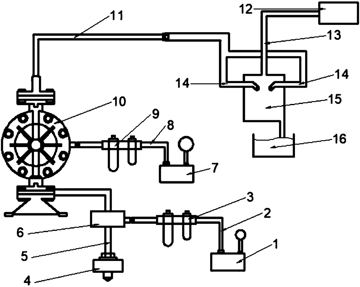
[0022] Such as figure 1 As shown, a splash type pneumatic degassing system includes a pneumatic diaphragm pump 10, and the pneumatic diaphragm pump 10 is also connected with a PLC automatic control system to realize the automatic operation of the pump and the automatic emptying of the pump when the pump is stopped; the pneumatic diaphragm pump The inlet end of 10 is connected with the mud suction port 4 through the A pipeline 5, and the pneumatic anti-blocking device 6 is arranged on the A pipeline 5, the lower end of the pneumatic anti-blocking device 6 enters the mud, and the upper end discharges the mud. The mud pipeline is blocked. When the pipeline is blocked, open the side port and pass in high-pressure gas to unblock it. The side port of the pneumatic anti-blocking device 6 is connected to the first air compressor 1 through the B pipeli...


PUM


Abstract

The invention relates to a splashing type pneumatic degassing system. The splashing type pneumatic degassing system comprises a pneumatic diaphragm pump, wherein an inlet end of the pneumatic diaphragm pump is connected with a mud suction port through a pipeline A, a pneumatic blockage preventer is arranged on the pipeline A, a side port of the pneumatic blockage preventer is connected with a first air compressor through a pipeline B, and a blockage preventer regulating valve is arranged on the pipeline B; a gas inlet of the pneumatic diaphragm pump is connected with a second air compressor through a pipeline C, and a mud pump regulating valve is arranged on the pipeline C; and an outlet end of the pneumatic diaphragm pump is connected with a degasser through a pipeline D. The degassing system disclosed by the invention has the advantages that compared with the traditional stirred degassing, the degassing is more efficient, meanwhile, the safety is greatly improved, and the workload ofmaintenance is reduced.

Description

technical field [0001] The invention belongs to the field of degassing for petroleum geological prospecting and logging, and in particular relates to a splash type pneumatic degassing system. Background technique [0002] The degasser is a widely used gas logging equipment in the process of modern oil exploration and drilling. Drilling fluid samples are collected from the drilling fluid flow returned to the ground, the dissolved and suspended gas is released, and the released gas is continuously sent to the gas detector for detection. With the in-depth study of mud logging technology and the continuous improvement of related equipment, the degasser is also continuously improved, and its degassing efficiency has also been significantly improved. The development of the degasser has generally experienced from non-dynamic degassing to dynamic degassing, from non-adaptive to adaptive degassing, from non-quantitative to quantitative degassing, from incomplete degassing components...

Claims


Application Information

Patent Timeline
Patent Type & Authority Applications(China)
IPC IPC(8): B01D19/00
CPCB01D19/0047B01D19/0063B01D19/0068
Inventor 梁海波刘子熠
Owner SOUTHWEST PETROLEUM UNIV
Why Eureka
Try Eureka