Automobile brake disc cleaning machine

A technology for automobile brakes and washing machines, applied in cleaning methods and tools, cleaning methods using liquids, cleaning methods using tools, etc., can solve the problems of insufficient friction between brake discs and brake pads, safety accidents affecting brake performance, and easy Dirty brake discs and other problems to achieve the effect of avoiding traffic accidents, fully cleaning, and improving the cleaning effect

Active Publication Date: 2020-09-29
CHONGQING IND POLYTECHNIC COLLEGE
View PDF8 Cites 0 Cited by
  • Summary
  • Abstract
  • Description
  • Claims
  • Application Information

AI Technical Summary

Problems solved by technology

However, since the brake disc is installed on the inner side of the wheel of the car, the car will splash dust and some other stains during driving, so it is extremely easy to dirty the brake disc
Stains on the brake disc will lead to insufficient friction between the brake disc and the brake block when the car is braking, which will affect the effectiveness of the brakes and even cause the brakes to fail, resulting in safety accidents
[0004] At present, most people clean the brake discs manually. However, this cleaning method is time-consuming and labor-intensive, and the cleaning cost is relatively high. Therefore, there is an urgent need for a device that can quickly clean the brake discs.

Method used


Image

  • Automobile brake disc cleaning machine
  • Automobile brake disc cleaning machine
  • Automobile brake disc cleaning machine

Examples


Embodiment 1

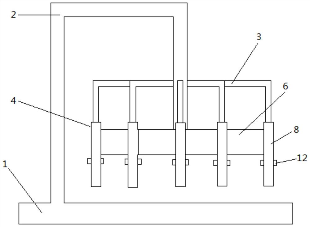
[0033] The embodiment is basically as attached figure 1 Shown: a car brake disc cleaning machine, including a cleaning table 1, a water outlet pipe 2, a cleaning part 4 and a motor. The motor is provided with a forward and reverse control switch and a one-way control switch.

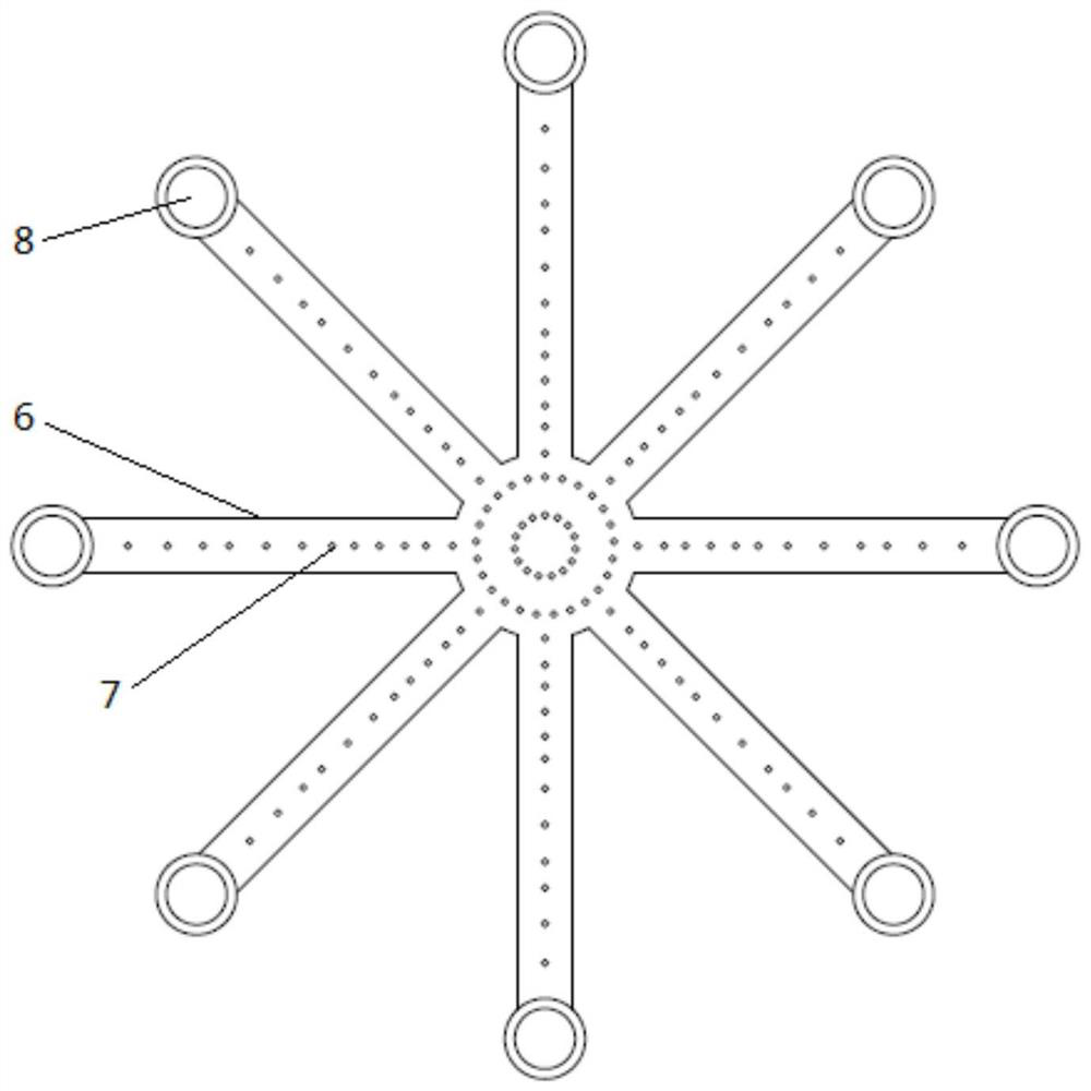
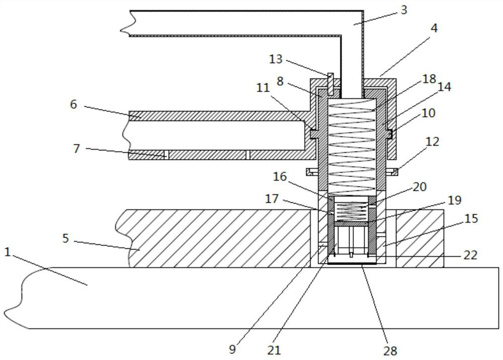
[0034] Such as figure 2 As shown, the cleaning part 4 includes several hollow brackets 6 and cleaning pipes 8 , and the middle part of the hollow brackets 6 is hingedly connected with the water outlet pipe 2 . A number of water outlet holes 7 are arranged on the lower end surface of the hollow support 6 . Such as image 3 As shown, the side wall of the cleaning pipe 8 is provided with a number of cleaning holes 9, the wall of the cleaning pipe 8 near the end of the water outlet pipe 2 is provided with a protrusion 10, and the hollow bracket 6 is provided with a groove 11 corresponding to the protrusion 10. . The hollow support 6 is connected in rotation with the cleaning pipe 8, and the outlet pipe ...

Embodiment 2

[0041] Such as Figure 7 As shown, the car brake disc cleaning machine, the difference between this embodiment and the above embodiment is that it is also provided with a rotating mechanism for rotating the cleaning part 4, including a connecting rod 29 connected with the motor and a dial for stirring the cleaning pipe 8 The rod 30 and the connecting rod 29 are fixedly connected with the motor. The driving rod 30 is provided with a chute 31 and a slot 32 . The driving rod 30 is slidably connected with the water pipe through the chute 31 .

[0042] During specific implementation, by setting the rotating mechanism as the connecting rod 26 connected with the motor and the driving rod 30 for stirring the cleaning pipe 8, the motor drives the connecting rod 29 to rotate so as to drive the driving rod 30 to rotate, and the driving rod 30 and the water pipe Relative sliding occurs, and due to the limitation of the length of the connecting rod 29, the driving rod 30 can only be rotate...

Embodiment 3

[0044] Such as Figure 8 As shown, the car brake disc cleaning machine, the difference between the present embodiment and the second embodiment is that the cleaning belt 22 is divided into two layers with different materials, wherein one layer is the cleaning layer 23, and its material is cotton cloth, and the other layer is soft magnetic Sheet 24.

[0045] During specific implementation, the cleaning belt 22 is divided into two layers with different materials, one of which is cotton cloth, and the other is a soft magnetic sheet 24 . Compared with the rubber material, the rubber has a higher density. When the cleaning pipe 8 rotates, the rubber may not be able to cling to the brake disc 5 due to the centrifugal force due to its own weight, and the purpose of cleaning cannot be achieved; the cotton material is lighter, and the cleaning pipe 8 When rotating, the cotton cloth is more likely to stick to the brake disc 5, which is convenient for cleaning, and the characteristics o...


PUM


Abstract

The invention belongs to the technical field of cleaning devices for cars, in particular to a cleaning machine for a brake disc of a car. The cleaning machine comprises a cleaning table, a water outlet pipe, a cleaning part and a motor. The cleaning part comprises a hollow support and cleaning pipes. Air outlet holes are arranged in the hollow support. The cleaning pipes are provided with cleaningholes and equipped with protrusions. Grooves are arranged in the hollow support. The cleaning pipes comprise hard pipe parts and flexible pipe parts. The interiors of the cleaning pipes are equippedwith sleeve pipes and first springs. The interiors of the sleeve pipes are equipped with baffle boards and second springs. The baffle boards are connected with upper end surfaces of the sleeve pipes through the second springs. Lower ends of the baffle boards are provided with extending rods. Cleaning strips are arranged on the extending rods. The cleaning pipes are also equipped with water lockingmechanisms used for controlling the cleaning pipes to open up and close down. The motor is equipped with a positively-reversely rotating control switch and a unilateral control switch. Positioning units used for fixing the cleaning pipes are installed between the cleaning pipes and the hollow support. By adoption of the scheme, the purpose of rapidly cleaning the brake disc is fulfilled. Trafficaccidents induced by brake failure due to dirt of the brake disc are avoided.

Description

technical field [0001] The invention belongs to the technical field of automobile cleaning devices, and in particular relates to an automobile brake disc cleaning machine. Background technique [0002] With the rapid development of social economy, automobiles have entered thousands of households, and more and more people choose automobiles as a means of transportation when they go out. Therefore, the driving safety of automobiles is particularly important. [0003] The car brake system is an extremely important part of the car, and the brake disc is an essential part of all car brake systems. The brake disc is fixed on the axle and rotates together with the wheel. When braking, the brake block is pressed onto the brake disc under the push of the clamp piston, and the wheel speed is reduced by the friction between the brake block and the brake disc to achieve the desired speed of the vehicle. The purpose of deceleration braking. However, since the brake disc is installed o...

Claims


Application Information

Patent Timeline
Patent Type & Authority Patents(China)
IPC IPC(8): B08B3/02B08B1/04
CPCB08B1/006B08B1/04B08B3/02
Inventor 苏涛欧阳刚陈冬俞燕苏姝欧阳桦
Owner CHONGQING IND POLYTECHNIC COLLEGE
Why Eureka
Try Eureka