Motor bracket stamping equipment

A technology for stamping equipment and motor brackets, applied in the field of stamping equipment for motor brackets, can solve problems such as damage to workpieces, and achieve the effect of reducing wear and tear

Active Publication Date: 2018-09-14
宁波高新区新柯保汽车科技有限公司
View PDF8 Cites 6 Cited by
  • Summary
  • Abstract
  • Description
  • Claims
  • Application Information

AI Technical Summary

Problems solved by technology

When the plate is deformed, the friction between the plate and the side wall of the mold cavity increases, so that when the upper mold exits the mold cavity, the formed workpiece will o...

Method used


Image

  • Motor bracket stamping equipment
  • Motor bracket stamping equipment

Examples


Embodiment Construction

[0021] The present invention will be described in further detail below by means of specific embodiments:

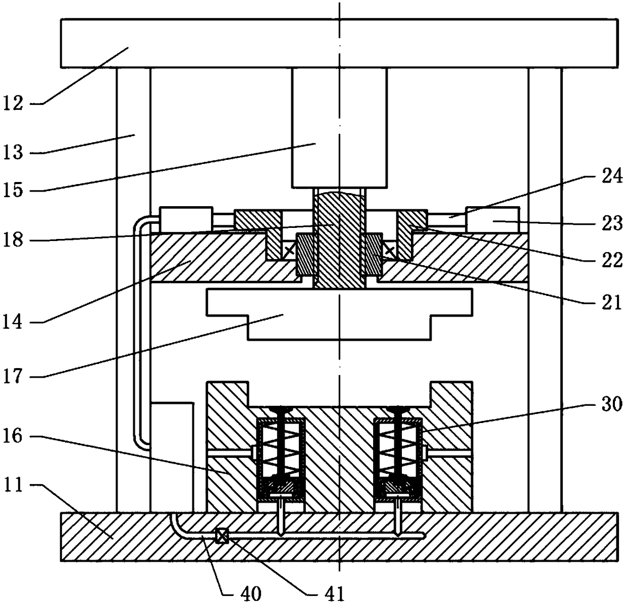
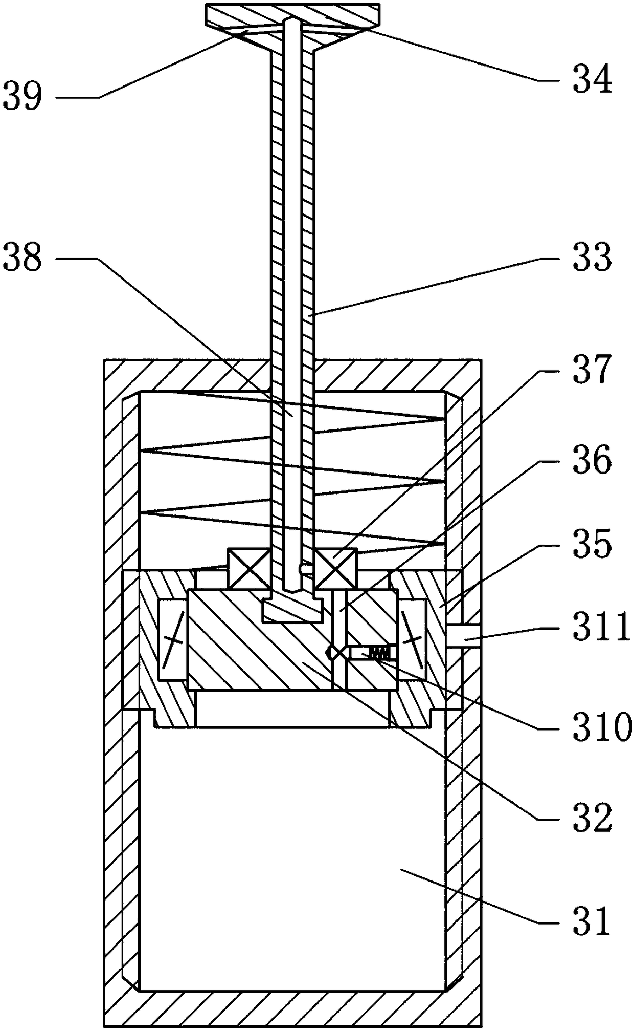
[0022] The reference signs in the drawings of the description include: base 11, top plate 12, column 13, mounting frame 14, stamping cylinder 15, die 16, punch 17, stamping rod 18, rotating ring 21, cam 22, pump 23 , push rod 24, ejection mechanism 30, cylinder body 31, piston 32, ejector rod 33, top block 34, control ring body 35, first exhaust hole 36, rotary joint 37, air passage 38, dust removal hole 39, plug Block 310 , second vent hole 311 .

[0023] The embodiment is basically as figure 1 , figure 2 Shown:

[0024] The stamping equipment for the motor bracket in this embodiment includes a base 11 and a top plate 12 , and the top plate 12 is fixed on the base 11 through a column 13 , thereby forming a stamping space between the top plate 12 and the base 11 . A stamping cylinder 15 is installed on the top plate 12, and the stamping cylinder 15 is connected to th...


PUM


Abstract

The application relates to the technical field of machining, and particularly discloses motor bracket stamping equipment. The motor bracket stamping equipment comprises a base and a top plate; a stamping cylinder is mounted on the top plate; the stamping cylinder is connected with a stamping rod; a female die is fixedly arranged on the base; a male die is fixed to the stamping rod; an ejection mechanism is arranged in the female die; an air collection mechanism is arranged at the periphery of the stamping rod; the air collection mechanism comprises a rotary ring body; when the stamping rod moves up and down, the rotary ring body can rotate in a reciprocating mode; the periphery of the rotary ring body is connected with a cam by a one-way bearing; an inflator is arranged at the periphery ofthe cam; the ejection mechanism comprises a cylinder body, a piston and an ejector rod; the piston can push the ejector rod to slide up and down; the ejector rod extends into a die cavity; a controlring body is arranged between the piston and the inner wall of the cylinder body; the control ring can also rotate in a reciprocating mode while moving up and down; the control ring body is connectedwith the piston by a one-way bearing; the piston is provided with a first vent hole; a plugging block capable of plugging the first vent hole is arranged in the piston; the middle part of the cylinderbody is provided with a second vent hole. The equipment can implement automatic demolding.

Description

technical field [0001] The invention relates to the technical field of mechanical processing, in particular to stamping equipment for a motor bracket. Background technique [0002] Stamping machinery is based on automation equipment and according to the characteristics of stamping production, it is specially developed for the realization of stamping automation and unmanned production. It can replace manual work in each stamping station for material stamping, handling, loading and unloading, and the efficiency of the entire production line reaches 5 seconds. For repetitive, dangerous and high-tempo processing industries such as stamping, this automation equipment can save labor costs, improve labor and equipment safety, and maintain product productivity, quality, and process stability. [0003] The mechanical stamping equipment is a mechanical stamping device that facilitates the withdrawal of stamping parts. The mechanical stamping device is mainly composed of an upper mold...

Claims


Application Information

Patent Timeline
IPC IPC(8): B21D22/02B21D45/02H02K15/14
CPCB21D22/02B21D45/02H02K15/14
Inventor 王作栋
Owner 宁波高新区新柯保汽车科技有限公司
Why Eureka
Try Eureka