A tubular casting and welding device

A casting-welding and tube-type technology is applied in the field of battery pole lug casting and welding devices, which can solve the problems of cumbersome battery production process and easy detachment of the pole group, and achieve the effects of avoiding difficulty in disassembly, facilitating fastening, and having a simple structure.

Active Publication Date: 2020-06-09
ANHUI ANLAN MOLD
View PDF9 Cites 0 Cited by
  • Summary
  • Abstract
  • Description
  • Claims
  • Application Information

AI Technical Summary

Problems solved by technology

In the above process, it is necessary to turn over the boxed pole group, so that the tabs are inserted downwards into the casting welding mold for casting and welding of the manifold. On the one hand, the entire battery production process is more cumbersome, and on the other hand, the pole group is easily come out

Method used


Image

  • A tubular casting and welding device
  • A tubular casting and welding device
  • A tubular casting and welding device

Examples


Embodiment 1

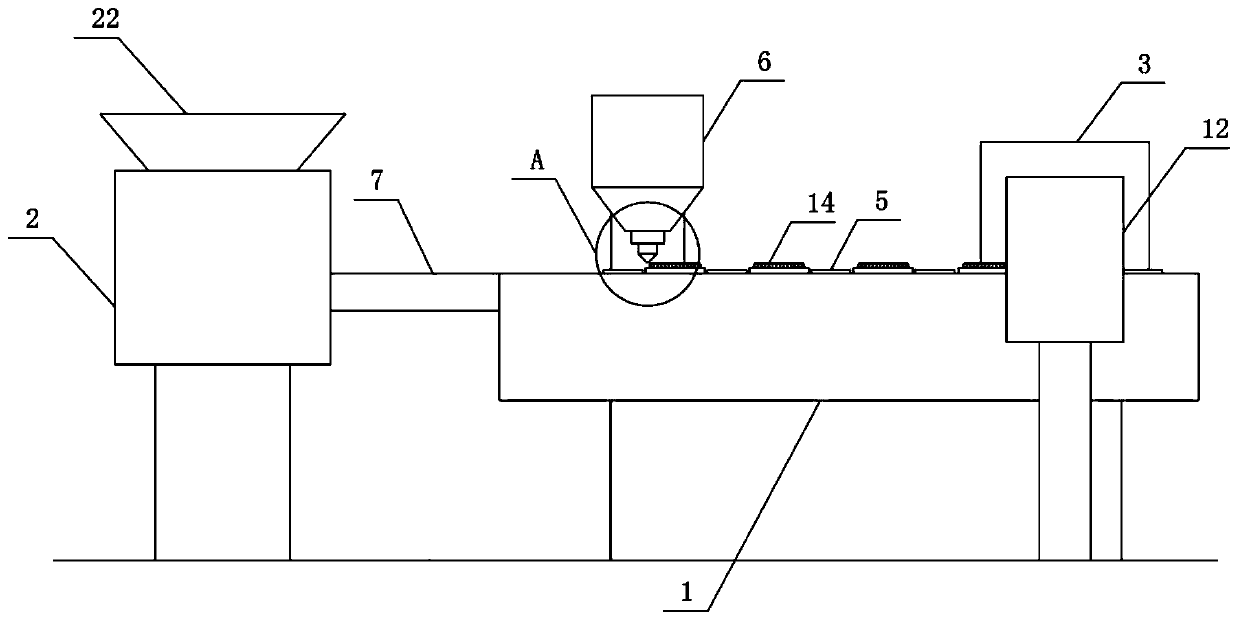
[0024] according to figure 1 A tubular casting and welding device shown includes a casting and welding station 1, a mold feeding device 2 and a tab feeding device 3. The setting of the mold feeding device 2 and the tab feeding device 3 is beneficial to the tab casting and welding mold 14 and the tabs are transported and sorted, so that the chaotically arranged tab casting molds 14 and the tabs are integrated, the mold feeding device 2 is set at one end of the casting station 1, and the tab feeding device 3 is set at the casting On one side of the other end of the soldering station 1, a liquid lead tank 6 is provided on one side of the casting and soldering station 1. The setting of the liquid lead tank 6 facilitates accurate measurement of the lead solution by a meter 19 and then transports it to the lug casting mold 14, compared with the traditional method of utilizing lead wire to melt, the lead liquid in the lead liquid tank 17 can be fully filled, avoiding the inconsistenc...

Embodiment 2

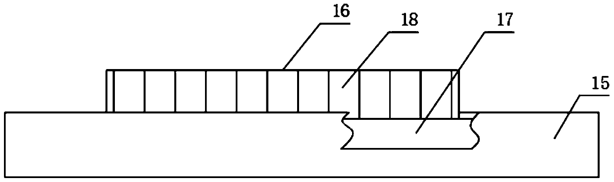
[0030] The difference from Example 1 is that the two side walls of the groove 21 are set at an inclination angle of 45° to 60°, which is conducive to the inclined setting of the vertically placed lug casting mold 14, and avoids the lead liquid tank 17. The lead liquid in the interior is not solidified, so that the bottom end of the tab falls into the bottom of the lead liquid tank 17, and the other end of the tab is exposed, resulting in low product quality.

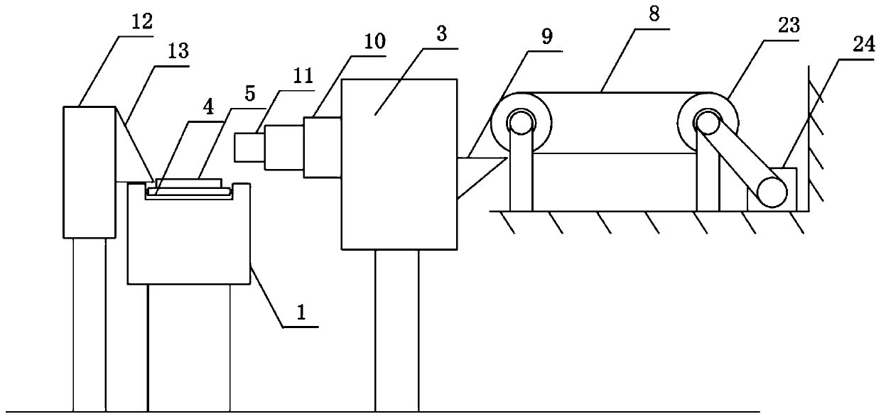
[0031]The working principle of the present invention: start the machine, each part starts to work, and the tab casting and welding mold 14 is transported from the mold feed port 22 to the mold feeding device 2, and the mold feeding device 2 carries out the process of receiving the chaotic tab casting and welding mold 14. Regularly transported to the conveying line 4 through the mold conveying platform 7 after sorting, and each tab casting mold 14 is arranged between adjacent partitions 5, and the tab is placed on the tab ...


PUM


Abstract

The invention discloses a tube type cast welding device. The device comprises a cast welding table, a die feeding device and a tab feeding device, the die feeding device is arranged at one end of thecast welding table, the tab feeding device is arranged on one side of the other end of the die feeding device, the top of the cast welding table is provided with a conveying line, a partition plate isfixedly arranged at the top of the conveying line, a lead liquid box is arranged on one side of the casting welding table, the lead liquid box is arranged between the die feeding device and the tab feeding device, a die conveying platform is arranged on one side of the die feeding device, and the input end of the die conveying platform is connected with the output end of the die feeding device. According to the device, through the production mode of the modular assembly line, all steps are separately processed, when a single part is damaged, only the damaged part need to be replaced, the disassembling difficulty is avoided, and moreover, the production efficiency can be greatly improved through the production mode of the assembly line.

Description

technical field [0001] The invention relates to the field of battery lug casting and welding devices, in particular to a tubular casting and welding device. Background technique [0002] The pole group of the lead-acid battery is composed of a number of positive plates and negative plates, and the positive tabs and negative tabs in the pole group are respectively connected through the bus plate. The existing tab casting and welding process is divided into pole group matching group, pole group boxing, pole group inversion and casting and welding manifold. In the above process, it is necessary to turn over the boxed pole group, so that the tabs are inserted downwards into the casting welding mold for casting and welding of the manifold. On the one hand, the entire battery production process is more cumbersome, and on the other hand, the pole group is easily come out. Therefore, it is necessary to invent a tubular casting welding device to solve the above problems. Contents...

Claims


Application Information

Patent Timeline
Patent Type & Authority Patents(China)
IPC IPC(8): B22D19/04
CPCB22D19/04
Inventor 王玉宝詹金珠洪家驹周勇董琪军
Owner ANHUI ANLAN MOLD
Why Eureka
Try Eureka