
Automatic laser cutting robot device

A technology of laser cutting and robotics, applied in the field of robotics, can solve the problems of inconvenient disassembly and maintenance, large manpower consumption, easy loosening of plugs and safety, etc., and achieves the effect of convenient operation and simple structure

Inactive Publication Date: 2018-09-14
福州鑫厦鑫计算机有限公司
View PDF2 Cites 0 Cited by
  • Summary
  • Abstract
  • Description
  • Claims
  • Application Information

AI Technical Summary

Problems solved by technology

[0002] At present, laser cutting robots are widely used. When using laser cutting robots, they need to be installed on the base. The traditional installation method is cumbersome and requires a lot of manpower. Moreover, it is not convenient for daily disassembly and maintenance. Additional plugs are used to connect to electricity, and the plugs are easy to loosen, causing potential safety hazards

Method used

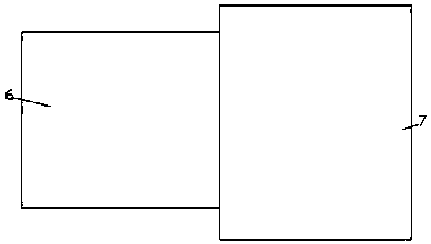
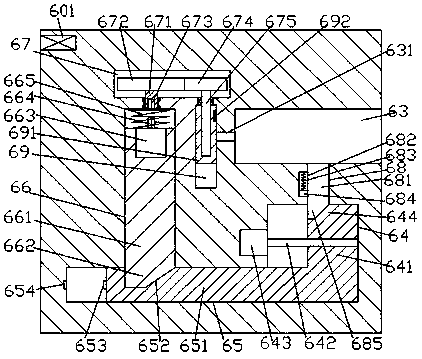
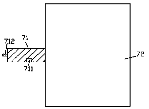

Image

  • Automatic laser cutting robot device
  • Automatic laser cutting robot device
  • Automatic laser cutting robot device

Examples


Embodiment Construction

[0014] Combine below Figure 1-3 The present invention will be described in detail.

[0015] refer to Figure 1-3 , an automatic laser cutting robot device according to an embodiment of the present invention, comprising a fixing seat 6 and a cutting machine body 7 for cooperating with the fixing seat 6, and the right end surface of the fixing seat 6 is provided with Inserting cavity 63, a first sliding cavity 64 is provided in the fixing seat 6 on the lower side of the inserting cavity 63, and the inner bottom wall of the first sliding cavity 64 communicates with a second sliding cavity extending to the left 65, the part between the insertion cavity 63 and the first sliding cavity 64 communicates with a first through groove 68, and the fixing seat 6 on the left side of the insertion cavity 63 is provided with a third sliding cavity 69 The fixing seat 6 on the left side of the third sliding chamber 69 is provided with a fourth sliding chamber 66 extending downwards, and the b...


PUM


Abstract

The invention discloses an automatic laser cutting robot device. The automatic laser cutting robot device comprises a mounting seat and a cutting machine body used for being connected with the mounting seat in a matched mode, an inserting cavity is formed in the right side end face of the mounting seat, a first sliding cavity is formed in the mounting seat at the lower side of the inserting cavity, the inner bottom wall of the first sliding cavity communicates with a second sliding cavity extending towards the left side, a first through groove is formed in the portion, between the inserting cavity and the first sliding cavity, a first through groove is formed in the portion, between the inserting cavity and the first sliding cavity, a third sliding cavity is formed in the mounting seat onthe left side of the inserting cavity, a fourth sliding cavity which extends downwards is arranged in the mounting seat on the left side of the third sliding cavity, the tail end of the bottom of thefourth sliding cavity communicates with the top of the left extending section of the second sliding cavity, a transmission cavity which extends to the right side is arranged in the mounting seat on the upper side of the fourth sliding cavity, and the right side extending section of the transmission cavity is located in the mounting seat on the upper side of the third sliding cavity.

Description

technical field [0001] The invention relates to the technical field of robots, in particular to an automatic laser cutting robot device. Background technique [0002] At present, laser cutting robots are widely used. When using laser cutting robots, they need to be installed on the base. The traditional installation method is cumbersome and requires a lot of manpower. Moreover, it is not convenient for daily disassembly and maintenance. Additional plugs are used to connect to electricity, and the plugs are easy to loosen and cause potential safety hazards. Contents of the invention [0003] The object of the present invention is to provide an automatic laser cutting robot device for overcoming the above-mentioned defects in the prior art. [0004] An automatic laser cutting robot device according to the present invention includes a fixing seat and a cutting machine body used to cooperate with the fixing seat, and an insertion cavity is provided in the right side end surfa...

Claims


Application Information

Patent Timeline
Patent Type & Authority Applications(China)
IPC IPC(8): B23K26/38B23K26/70
CPCB23K26/38B23K26/70B23K26/702
Inventor 李文祥
Owner 福州鑫厦鑫计算机有限公司
Learn More