
Tool holder with automatic tool changing function for converting external cooling into turning internal cooling

A technology of automatic tool change and tool holder, applied in the direction of clamping, support, positioning device, etc., can solve the problems of difficult to reach cutting fluid or coolant, damage to workpiece and tool, and inability to spray.

Pending Publication Date: 2018-09-14
广东希普斯科技有限公司
View PDF8 Cites 3 Cited by
  • Summary
  • Abstract
  • Description
  • Claims
  • Application Information

AI Technical Summary

Problems solved by technology

At present, the tool cooling method is usually external cooling. When deep drilling the workpiece, it is difficult for the cutting fluid or coolant to reach the tip of the tool or the spraying intensity of the coolant is too low to be sprayed on the tip of the tool. The cooling effect is poor and cannot Effectively flushes debris, causing some damage to workpieces and tools
In the existing technology, there is also an internally cooled tool handle, but the injection method of cutting fluid or coolant is generally a linear injection, and the cooling effect is not good enough, so it cannot be used for automatic tool change.

Method used


Image

  • Tool holder with automatic tool changing function for converting external cooling into turning internal cooling
  • Tool holder with automatic tool changing function for converting external cooling into turning internal cooling
  • Tool holder with automatic tool changing function for converting external cooling into turning internal cooling

Examples


Embodiment Construction

[0027] In order to facilitate the understanding of those skilled in the art, the present invention will be further described below in conjunction with the embodiments and accompanying drawings, and the content mentioned in the implementation mode is not to limit the present invention. The present invention is described in detail below in conjunction with accompanying drawing.

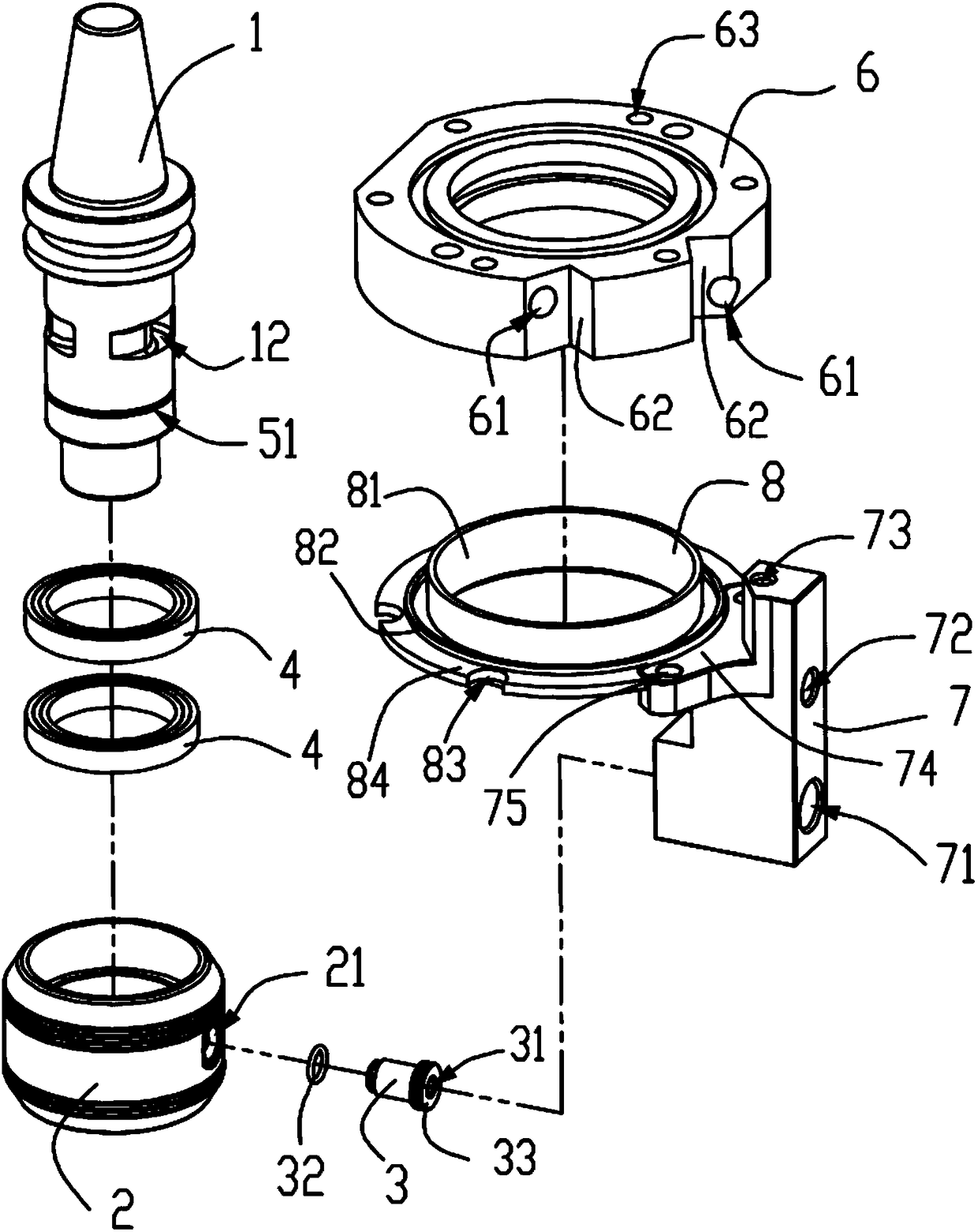
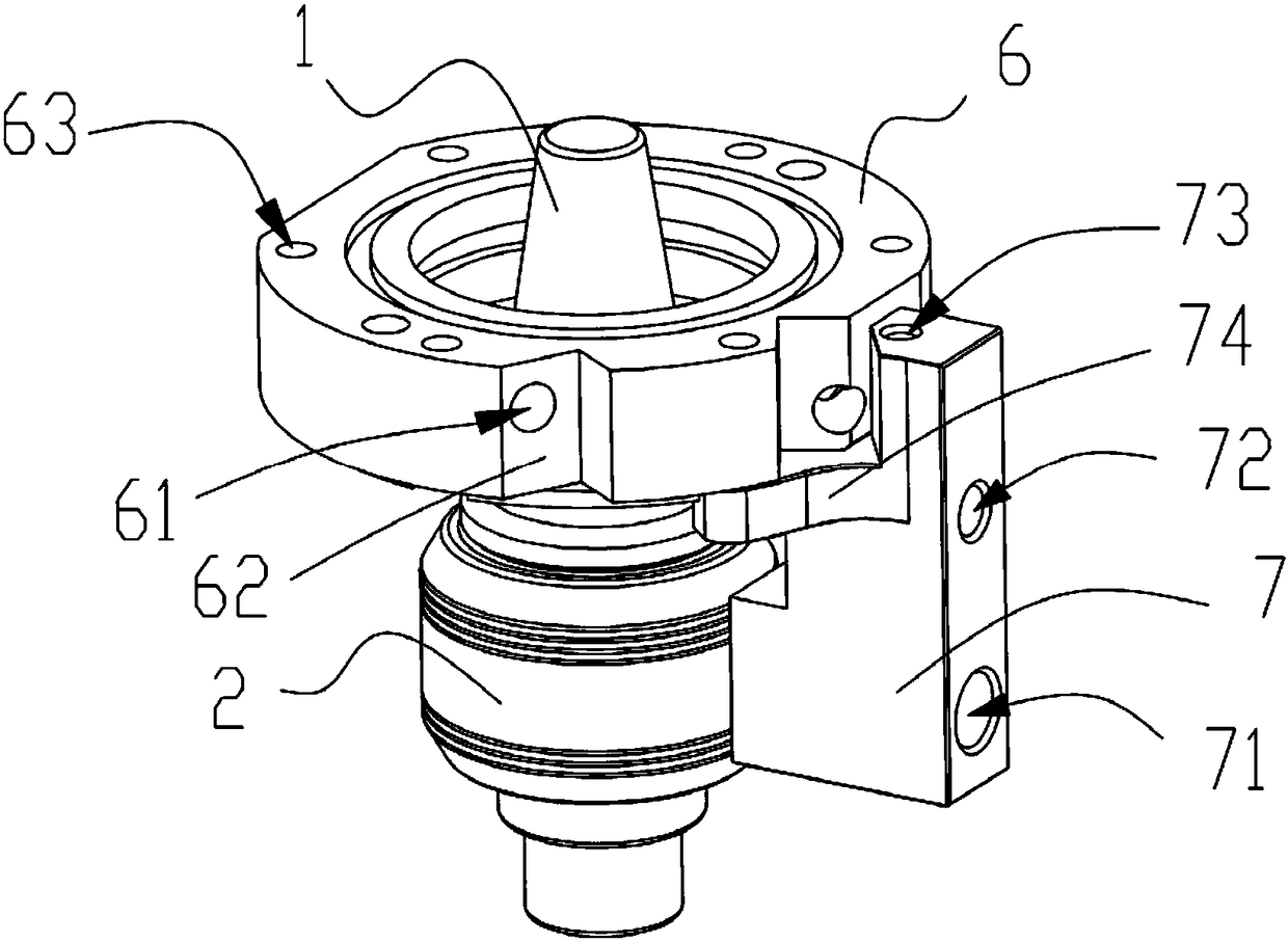
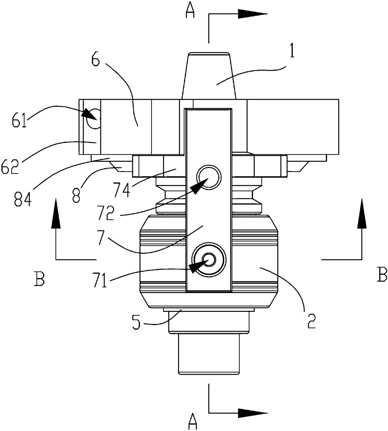
[0028] see Figures 1 to 9 As shown in the figure, the present invention provides a knife handle for automatic tool change from external cooling to internal cooling, including a knife handle main body 1, a connecting part 6 and a bracket base 7 fixedly connected to the connecting part 6, the knife The handle main body 1 is rotationally connected with the bracket base 7, one end of the handle main body 1 passes through the connecting part 6, and the handle main body 1 is provided with a tool installation blind hole 11 and a liquid inlet through hole 12. The tool installation blind hole 11 is arranged at...


PUM


Abstract

The invention relates to the technical field of tool fixing parts, in particular to a tool holder with the automatic tool changing function for converting external cooling into turning internal cooling. The tool holder comprises a tool holder main body, a connecting support base and a support base, wherein the support base is fixedly connected to the connecting part; the tool holder main body is connected to the support base in a rotating mode; one end of the tool holder main body penetrates through the connecting part; a tool mounting blind hole and a liquid inlet through hole are formed in the tool holder main body; the liquid inlet through hole is in an arc shape; and the support base is provided with a pressurization through hole used for communicating with the liquid inlet through hole. According to the tool holder, cutting fluid or cooling liquid spirally entering the tool mounting blind hole generates eddies, so that the cooling effect on the tool can be improved; the cutting fluid or the cooling liquid can reach the tip of the tool along a through hole of the tool when an external workpiece is subjected to deep drilling, so that the cooling effect is good, and chippings canbe effectively washed; and automatic tool changing can be realized, the service performance of the tool can be improved, the workpiece and the tool can be effectively protected, the service life of the tool can be prolonged, and the reliability can be improved.

Description

technical field [0001] The invention relates to the technical field of tool holders and tools, in particular to a tool holder for automatic tool change from external cooling to internal cooling. Background technique [0002] The tool rotates at high speed during processing, which generates a lot of heat, and the temperature of the tool increases, which can easily lead to tool damage, so it is necessary to cool the working tool. At present, the tool cooling method is usually external cooling. When deep drilling the workpiece, it is difficult for the cutting fluid or coolant to reach the tip of the tool or the spraying intensity of the coolant is too low to be sprayed on the tip of the tool. The cooling effect is poor and cannot Effectively flush debris, causing certain damage to workpieces and cutting tools. In the prior art, there is also a tool handle with internal cooling, but the injection mode of cutting fluid or coolant is generally linear injection, and the cooling ef...

Claims


Application Information

Patent Timeline
Patent Type & Authority Applications(China)
IPC IPC(8): B23Q3/12B23Q11/10
CPCB23Q3/12B23Q11/10
Inventor 叶新昌
Owner 广东希普斯科技有限公司
Learn More