
Cutting device for cutting tire components

A cutting device and component technology, applied in metal processing and other directions, can solve the problems of low cutting efficiency, occurrence, accidental damage, etc., and achieve the effect of simple structure and easy use.

Inactive Publication Date: 2018-09-14
宁波鄞州台本荣机械设备有限公司
View PDF5 Cites 0 Cited by
  • Summary
  • Abstract
  • Description
  • Claims
  • Application Information

AI Technical Summary

Problems solved by technology

In the preliminary processing of tires, cutting devices are often used to cut rubber materials, but the traditional rubber cutting devices not only have low cutting efficiency, but also their cutting blades are generally exposed to the outside world. It often causes accidental damage. In addition, after the cutting process is completed, the cutting blade will rotate for a period of time under the action of inertia, which often causes safety accidents. There are large safety hazards and need to be improved.

Method used


Image

  • Cutting device for cutting tire components
  • Cutting device for cutting tire components

Examples


Embodiment Construction

[0017] All features disclosed in this specification, or steps in all methods or processes disclosed, may be combined in any manner, except for mutually exclusive features and / or steps.

[0018] Any feature disclosed in this specification (including any appended claims, abstract and drawings), unless expressly stated otherwise, may be replaced by alternative features which are equivalent or serve a similar purpose. That is, unless expressly stated otherwise, each feature is one example only of a series of equivalent or similar features.

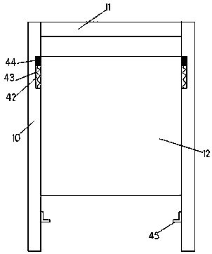
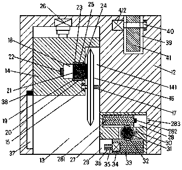
[0019] Such as Figure 1-2 As shown, a cutting device for cutting tire parts of the device of the present invention includes a left-right symmetrical support frame 10 extending up and down and a body 12 that can slide up and down between the two support frames 10, two A horizontal frame 11 is fixedly connected between the tops of the support frame 10, a first sliding groove 13 extending up and down and opening downward is provided in the body...


PUM


Abstract

The invention relates to a cutting device for cutting tire components. The cutting device for cutting the tire components comprises left-and-right symmetric support frames extending up and down, and amachine body arranged between the two support frames in an up-and-down sliding way; a horizontal frame is fixedly connected between the top parts of the two support frames; a first sliding chute extending up and down and provided with a downward opening is formed in the machine body; a first sliding block is slidably arranged in the first sliding chute; a first rotating cavity communicating withthe first sliding chute is arranged in the right side end surface of the first sliding block; a cutting blade is rotatably arranged in a left side inner wall of the first rotating cavity through a first rotating shaft; the right side end of the first rotating shaft penetrates through the right side end surface of the cutting blade; a spline shaft is fixedly arranged at the right side tail end of the first rotating shaft; and a second sliding chute with an opening facing the first rotating cavity is formed in a position, located on the upper part of the first rotating shaft, in the left side inner wall of the first rotating cavity.

Description

technical field [0001] The invention relates to the technical field of tire processing and production, in particular to a cutting device for cutting tire components. Background technique [0002] Tires are circular elastic rubber products that roll on the ground and are assembled on various vehicles or machinery. Half of the rubber consumed in the world is used for tire production, which shows the ability of tires to consume rubber. In the preliminary processing of tires, cutting devices are often used to cut rubber materials, but the traditional rubber cutting devices not only have low cutting efficiency, but also their cutting blades are generally exposed to the outside world. Often can cause accidental damage, in addition after cutting process is finished, owing to its cutting blade also can rotate a period of time under the effect of inertia, often can cause the generation of safety accident, there is bigger potential safety hazard, needs improvement. Contents of the...

Claims


Application Information

Patent Timeline
Patent Type & Authority Applications(China)
IPC IPC(8): B26D1/18B26D5/04B26D5/08B26D7/24B26D7/26
CPCB26D1/18B26D5/04B26D5/086B26D7/24B26D7/26B26D7/2635B26D2007/2657
Inventor 曾棣
Owner 宁波鄞州台本荣机械设备有限公司
Learn More