Non-launder copper alloy converter with quick head changing traction device

A traction device and copper alloy technology, applied in the field of launderless copper alloy converters, can solve problems such as inability to replace in time, volatilization of volatile metals, unqualified product quality, etc., and achieve reasonable facility setting, improved production efficiency, and convenient operation. Effect

Pending Publication Date: 2018-09-14
安徽品志合金新材料有限公司 +1
View PDF7 Cites 1 Cited by
  • Summary
  • Abstract
  • Description
  • Claims
  • Application Information

AI Technical Summary

Problems solved by technology

The disadvantage of this production process is: copper water has a large amount of heat loss in the converter process of "melting furnace → launder → holding furnace", and also causes a large amount of volatilization of volatile metals, not only waste of raw materials and energy, but also will seriously pollute the environment
In addition, the current horizontal continuous casting of copper and copper alloys uses multiple heads to draw copper alloys to improve production efficiency. However, during the drawing process, if a wire billet fails and the product quality is unqualified, it cannot be replaced in time. The drawing casting can only be stopped below the casting line of the holding furnace for replacement
In this way, continuous production cannot be fully realized, which will affect production efficiency.

Method used


Image

  • Non-launder copper alloy converter with quick head changing traction device
  • Non-launder copper alloy converter with quick head changing traction device
  • Non-launder copper alloy converter with quick head changing traction device

Examples


Embodiment Construction

[0033] The specific implementation of the troughless copper alloy converter with quick-change head pulling device of the present invention will be further described below in conjunction with the accompanying drawings, but it should be pointed out that the implementation of the present invention is not limited to the following embodiments.

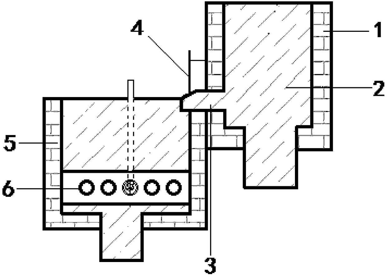
[0034] see figure 1 . A troughless copper alloy converter with a quick head change traction device, comprising a melting furnace 1, a melting furnace copper water 2, a graphite discharge seat 3, a first flow control rod 4, a holding furnace 5 and a quick head change hole 6, the Described melting furnace 1 and holding furnace 5 can adopt existing equipment. The melting furnace 1 and the holding furnace 5 are set in a form that the melting furnace 1 is high and the holding furnace 5 is low, and the furnace wall between the melting furnace 1 and the holding furnace 5 is arranged in a connected form. 1 The graphite discharge seat 3 is arrange...


PUM


Abstract

The invention discloses a non-launder copper alloy converter with a quick head changing traction device. A melting furnace and an insulation furnace are arranged to be in a form that furnace walls areconnected, the front portion is high and the back portion is low; a graphite releasing base containing a releasing hole and a releasing groove is arranged on the lower furnace wall of the melting furnace and the upper furnace wall of the insulation furnace; the melting furnace is connected behind the graphite releasing base; the insulation furnace is connected before the graphite releasing base;the flow of molten copper of the melting furnace is controlled by a first flow control rod; the quick head changing traction device consisting of a graphite control base, a graphite crystallizer, a crystallizer copper sleeve, a crystallizer steel cover and a cooling water cavity can sleeve the front end of the insulation furnace by a quick head changing hole; and the flow of molten copper of the insulation furnace is controlled by a second control rod. In the converter without a launder, the molten copper of the melting furnace nearly enters the insulation furnace directly without high heat and great volatilization of volatile metal; once towed wire blanks do not meet requirements, the traction can be immediately stopped to replace equipment, so that the staff and equipment safety is guaranteed; and the converter is safe, capable of saving energy, environmentally friendly and low in cost, and can improve the production efficiency of copper and copper alloy wire blanks.

Description

technical field [0001] The invention relates to the technical field of horizontal continuous casting of copper and copper alloys, in particular to a launderless copper alloy converter with a quick head-changing traction device for producing copper and copper alloy wire blanks. Background technique [0002] At present, the production method of copper and copper alloy wire billet is: "melting furnace → launder → holding furnace → horizontal continuous casting → wire billet" production process. The disadvantage of this production process is: copper water has a large amount of heat loss in the converter process of "melting furnace → launder → holding furnace", and also causes a large amount of volatilization of volatile metals, not only waste of raw materials and energy, but also It will seriously pollute the environment. In addition, the current horizontal continuous casting of copper and copper alloys uses multiple heads to draw copper alloys to improve production efficiency....

Claims


Application Information

Patent Timeline
Patent Type & Authority Applications(China)
IPC IPC(8): C22B15/06B22D11/00
CPCC22B15/006B22D11/004B22D11/005
Inventor 封昌干赵国天
Owner 安徽品志合金新材料有限公司
Why Eureka
Try Eureka