A kind of energy-saving furnace with cyclone generating device

A technology of generating device and energy-saving furnace, which is applied to household stoves/stoves, household cooking utensils, combustion methods, etc., can solve the problems of short delivery time, gas loss, insufficient mixing and combustion, and achieve longer mixing time and mixing path. , the effect of long burning time

Inactive Publication Date: 2011-11-30
曾文洲
View PDF6 Cites 7 Cited by
  • Summary
  • Abstract
  • Description
  • Claims
  • Application Information

AI Technical Summary

Problems solved by technology

[0002] Gas stoves are commonly used stoves in many places, and the number of applications is extremely large. Gas stoves consume gas to generate heat for use. In the context of resource shortages, the energy-saving performance of stoves is particularly important. When the stove is working, the gas burns fully. Whether or not it is the key factor affecting the energy-saving effect, and the sufficient mixing of gas and air is an important guarantee for sufficient combustion. The existing various energy-saving stoves often ignore the importance of the mixing of gas and air, so there are different degrees of Technical defects, the existing energy-saving stoves, in the structure of gas and air supply, all adopt the way of gas and air passing directly to the combustion zone for combustion, that is, the gas and air rise vertically in the conveying channel and directly pass into the combustion zone for combustion, and the gas The common transportation path and transportation time with air are extremely short, so the mixing of gas and air before combustion is extremely limited, which is not enough to meet the conditions of full combustion. , the purpose of energy saving cannot be achieved, and in the combustion zone, the gas and air are not fully mixed, so that a large amount of gas is dense and a large amount of air is dense, resulting in extremely unstable combustion, frequent flameouts, and poor use effects
[0003] In summary, the existing gas stoves have technical defects such as insufficient mixing and combustion, gas loss, unstable combustion, and poor energy-saving effect

Method used


Image

  • A kind of energy-saving furnace with cyclone generating device
  • A kind of energy-saving furnace with cyclone generating device
  • A kind of energy-saving furnace with cyclone generating device

Examples


Embodiment 1

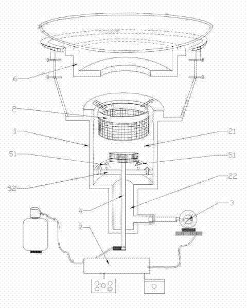
[0022] Such as figure 1As shown, the present invention includes a furnace chamber 6, a furnace chamber 1, a reticulated furnace core 2, and a blower fan 3. The furnace chamber 1 is made of a high-temperature-resistant material, and the furnace chamber 1 is connected to the bottom of the furnace chamber 6. The furnace chamber 1 The upper part is a gas and air rotary mixing zone 21, and the lower part is an air intake zone 22. The mesh furnace core 2 is arranged above the gas and air rotary mixing zone 21 in the furnace chamber 1, and the fan 3 and the The air intake area 22 of the furnace cavity 1 communicates, and the fan 3 provides the air required for combustion. The furnace cavity 1 is provided with a gas channel 4, and the end of the gas channel 4 is connected to the gas supply device outside the energy-saving furnace ( Such as a gas bottle), the gas channel 4 extends into the gas and air rotary mixing zone 21 to input the gas required for combustion. The present invention...

Embodiment 2

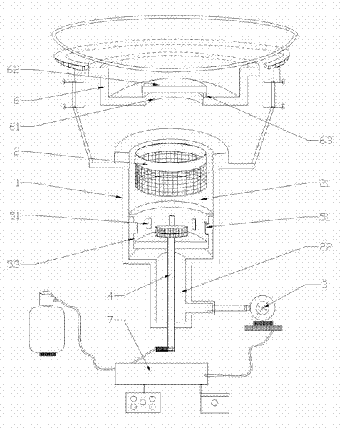
[0024] Such as figure 2 As shown, in this embodiment, the cyclone generating device includes a vertical straight plate 53, and several of the air outlet nozzles 51 are distributed on the side wall of the vertical straight plate 53 along the circumference, and the air intake area 22 passes through the The air outlet nozzle 51 communicates with the gas and air rotary mixing area 21 .

[0025] In this embodiment, on the basis of the cyclone generating device, the structure of the cover plate 62 is added. In the implementation, the pot is adapted to the upper part of the furnace 6, and a combustion through hole 61 is opened at the bottom of the furnace 6. A cover plate 62 made of a high-temperature-resistant material is arranged above the combustion through hole 61, and a gap is formed between the cover plate 62 and the bottom of the furnace 6 through a bracket device, and the furnace chamber 1 is connected to the furnace chamber 1 through the gap. The furnace 6 communicates, th...

Embodiment 3

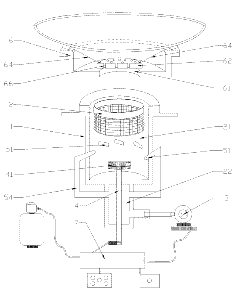
[0028] Such as image 3 As shown, in this embodiment, the cyclone generating device includes a plurality of ventilation pipes 54, one end of the ventilation pipes 54 communicates with the air intake area 22, and the other end is an air outlet nozzle 51, and the air outlet nozzle 51 is inserted obliquely The outer wall of the furnace cavity 1 extends into the air and gas rotary mixing zone 21 , and the air intake zone 22 communicates with the gas and air rotary mixing zone 21 through the air outlet nozzle 51 of the air pipe 54 .

[0029] In this embodiment, the cover plate 62 is provided with several through holes 51, and the flame in the first combustion chamber can directly enter the first combustion chamber through the through holes 66 of the cover plate 62 to heat the pot. . The diameter of the through hole 66 is 4mm˜40mm.

[0030] In this embodiment, the support device is a fixed stay rope 64, one end of the fixed stay rope 64 is fixedly connected to the cover plate 62, ...


PUM


Abstract

The invention discloses an energy-saving furnace with a cyclone generating device, aiming to provide an energy-saving furnace with more complete mixing and combustion, more stable combustion, higher safety and better energy-saving effect. The invention comprises a furnace (6), a furnace chamber (1), a mesh furnace core (2), a blower fan (3), and a cyclone generator. The upper part of the furnace chamber (1) is a gas and air rotating mixing zone (21), and the lower part is The air intake area (22), the mesh furnace core (2) is arranged above the gas and air rotating mixing area (21) in the furnace chamber (1), the fan (3) communicates with the air intake area (22), and the furnace chamber ( 1) There is a gas channel (4) extending into the gas and air rotating mixing area (21), and the cyclone generating device includes several air outlet nozzles (51) arranged in the gas and air rotating mixing area (21). (51) are distributed in a circle and inclined in the same direction. The air outlet nozzle (51) is a passage connecting the air intake area (22) and the gas and air rotating mixing area (21). The air outlet direction of the air outlet nozzle (51) is uniform Either clockwise or counterclockwise. The invention can be widely used in the field of stoves.

Description

technical field [0001] The invention relates to an energy-saving furnace with a cyclone generating device. Background technique [0002] Gas stoves are commonly used stoves in many places, and the number of applications is extremely large. Gas stoves consume gas to generate heat for use. In the context of resource shortages, the energy-saving performance of stoves is particularly important. When the stove is working, the gas burns fully. Whether or not it is the key factor affecting the energy-saving effect, and the sufficient mixing of gas and air is an important guarantee for sufficient combustion. The existing various energy-saving stoves often ignore the importance of the mixing of gas and air, so there are different degrees of Technical defects, the existing energy-saving stoves, in the structure of gas and air supply, all adopt the way of gas and air passing directly to the combustion zone for combustion, that is, the gas and air rise vertically in the conveying channe...

Claims


Application Information

Patent Timeline
Patent Type & Authority Applications(China)
IPC IPC(8): F24C3/00F23D14/62
CPCY02B40/166Y02B40/00
Inventor 曾文洲
Owner 曾文洲
Why Eureka
Try Eureka