Ring plate splicing type hollow sandwich concrete-filled steel tube composite joint and installation method

A technology of steel pipe concrete and combined joints, which is applied in the direction of construction and building construction, can solve the problems of heavy welding workload, unguaranteed welding quality, inconvenient transportation and construction, etc., so as to improve seismic performance, increase labor productivity, and avoid quality problems. problem effect

Active Publication Date: 2018-09-14
QINGDAO TECHNOLOGICAL UNIVERSITY
View PDF5 Cites 15 Cited by
  • Summary
  • Abstract
  • Description
  • Claims
  • Application Information

AI Technical Summary

Problems solved by technology

Since the outer ring plate is easily damaged during transportation, it needs to be welded with the steel beam flange plate on site, resulting in a large welding workload on site and the welding quality cannot be guaranteed, making transportation and construction inconvenient

Method used


Image

  • Ring plate splicing type hollow sandwich concrete-filled steel tube composite joint and installation method
  • Ring plate splicing type hollow sandwich concrete-filled steel tube composite joint and installation method
  • Ring plate splicing type hollow sandwich concrete-filled steel tube composite joint and installation method

Examples


Embodiment 1

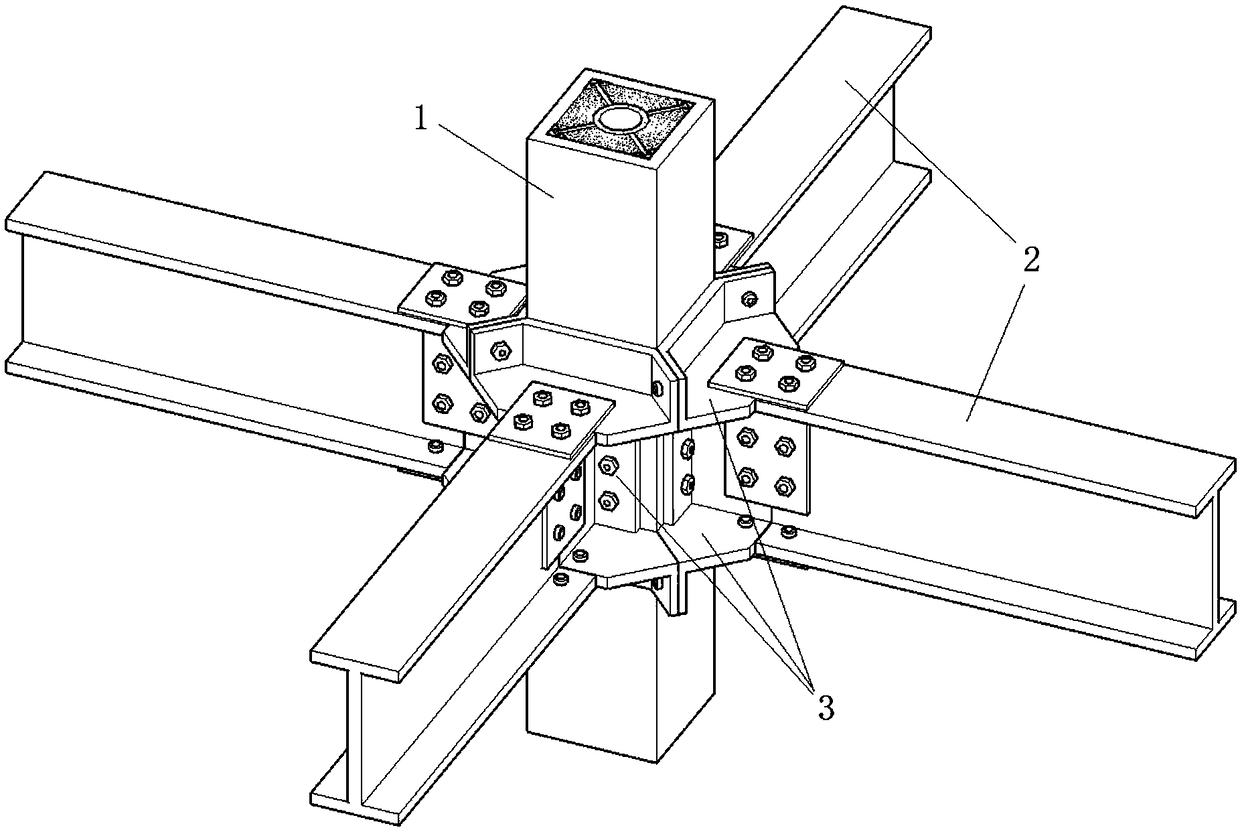
[0043] Such as figure 1 As shown, the ring plate spliced ​​hollow interlayer concrete filled steel tube composite node of the present invention includes a square steel tube column 1, an I-shaped steel beam 2 and a beam-column connection assembly 3 connecting the two;

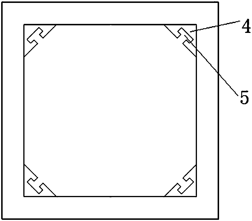
[0044] Such as figure 2 As shown, the four corners of the square steel pipe column are fixed with connecting corner posts 4. The cross section of the connecting corner posts is an isosceles triangle, and the corners on both sides are respectively fixed at the four corners of the inner wall of the square steel pipe column by spot welding. , the connecting corner post is provided with a vertically through T-shaped hole 5;

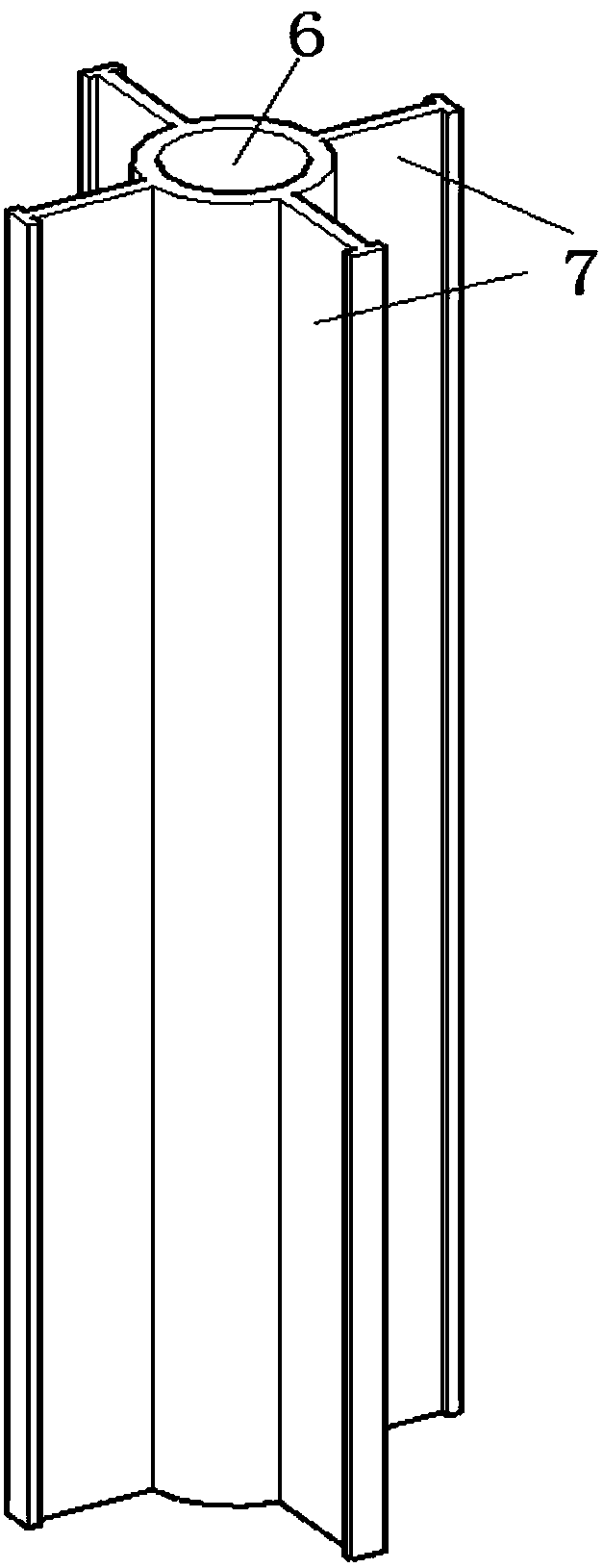
[0045] Such as image 3 As shown, the center of the square steel pipe column is provided with a round steel pipe column 6, and four T-shaped connecting side plates 7 are evenly distributed on the round steel pipe column, and the adjacent T-shaped connecting side plates are perpendicular to e...

Embodiment 2

[0058] Such as Figure 9 As shown, the difference between this embodiment and embodiment 1 is that in this embodiment, each group of splicing plates includes two splicing plates, one of which is the same as the standard splicing plate in embodiment 1, and the other is made of the standard splicing plate in embodiment 1. The three standard splicing plates are integrated into one to form a C-shaped splicing plate, the connecting ears at both ends are reserved, and the connecting ears of the other standard splicing plate are connected by high-strength bolts.

[0059] Since the three-in-one splicing plate can only be slid in from one direction (the direction opposite to another standard splicing plate), only one T-shaped slider in the middle can be reserved. Correspondingly, it only needs to be in the corresponding A T-shaped chute is arranged on the T-shaped connecting piece on one side, and there is no need to set a T-shaped chute on the T-shaped connecting pieces on the other t...

Embodiment 3

[0061] Such as Figure 10 As shown, the difference between this embodiment and Embodiment 1 is that in this embodiment, each group of splicing plates includes two identical splicing plates, and each splicing plate is formed by combining two standard splicing plates in Embodiment 1. , become a semi-enclosed splicing plate, retain the connecting ears at both ends, and connect the connecting ears of two half-enclosed splicing plates through high-strength bolts.

[0062] The two-in-one splicing plate can be slid in from one of two directions, so one of the original two T-shaped sliders on each splicing plate can be retained, and the other can be removed. The T-shaped chute on the connecting piece is reserved, and there is no need to set the T-shaped chute on the other T-shaped connecting pieces. The semi-enclosed splicing panels are also prefabricated in advance in the factory as standard parts, and can be assembled on site. Others are the same as in Example 1.


PUM


Abstract

The invention relates to the technical field of connection of building structures, and discloses a ring plate splicing type hollow sandwich concrete-filled steel tube composite joint and an installation method. The composite joint comprises a square steel tube column, an I-shaped steel beam and beam-column connecting assemblies connecting the square steel tube column and the I-shaped steel beam, wherein the square steel tube column is connected with T-shaped connecting side plates of a round steel tube column through T-shaped holes in a matching manner; each beam-column connecting assembly comprises an upper group and a lower group of splicing plates which are symmetrically arranged and a T-shaped connecting piece which is arranged between the two groups of splicing plates and connects thetwo groups of splicing plates; each group of the splicing plates comprises four identical splicing plates, wherein each splicing plate comprises a horizontal part, a vertical part and a connecting lug, and the back surface of the horizontal part is provided with a T-shaped slider; each T-shaped connecting piece is provided with a T-shaped sliding groove matched with the T-shaped slider. The position of a central steel pipe column is fixed, connecting joints are spliced and connected by special outer ring plates, and a design concept of 'strong column and weak beam' is realized; the welding ofall components was completed in a factory and all the components are connected by bolts on site, and thus a complete assembly construction is realized.

Description

technical field [0001] The invention relates to the technical field of connection of building structures, in particular to a ring plate spliced ​​hollow interlayer concrete filled steel tube composite node and an installation method. Background technique [0002] Steel structure buildings have the characteristics of high strength, light weight, fast construction speed, good seismic performance and high degree of industrialization. Steel structural components form a structural system by connecting nodes, and the choice of node form has a direct impact on structural integrity, reliability, construction period, and the design and construction of auxiliary components. [0003] The outer ring plate joint is a common joint form, mainly composed of ring plate, web shear connection plate, steel pipe column, steel beam and so on. A common form of steel pipe column is the hollow interlayer concrete-filled steel pipe column. The hollow interlayer concrete-filled steel pipe column is a...

Claims


Application Information

Patent Timeline
Patent Type & Authority Applications(China)
IPC IPC(8): E04B1/30E04B1/58
Inventor 牟犇王君昌罗云标侯东帅苏雷
Owner QINGDAO TECHNOLOGICAL UNIVERSITY
Why Eureka
Try Eureka