Cloth dehydrator with self-adaptive damping device

A shock absorber and dehydrator technology, applied in the direction of springs/shock absorbers, support machines, mechanical equipment, etc., can solve problems such as automatic adjustment of the shock absorber effect of the shock absorber

Active Publication Date: 2018-09-14
宁波隆锐机械制造有限公司
View PDF10 Cites 5 Cited by
  • Summary
  • Abstract
  • Description
  • Claims
  • Application Information

AI Technical Summary

Problems solved by technology

[0005] The present invention intends to provide a fabric dehydrator with an adaptive damping device to overcome the problem that the dehydrator damping device in the prior art cannot automatically adjust the damping effect of the damper according to the vibration frequency of the dehydrator

Method used


Image

  • Cloth dehydrator with self-adaptive damping device
  • Cloth dehydrator with self-adaptive damping device
  • Cloth dehydrator with self-adaptive damping device

Examples


Embodiment Construction

[0017] The present invention will be described in further detail below by means of specific embodiments:

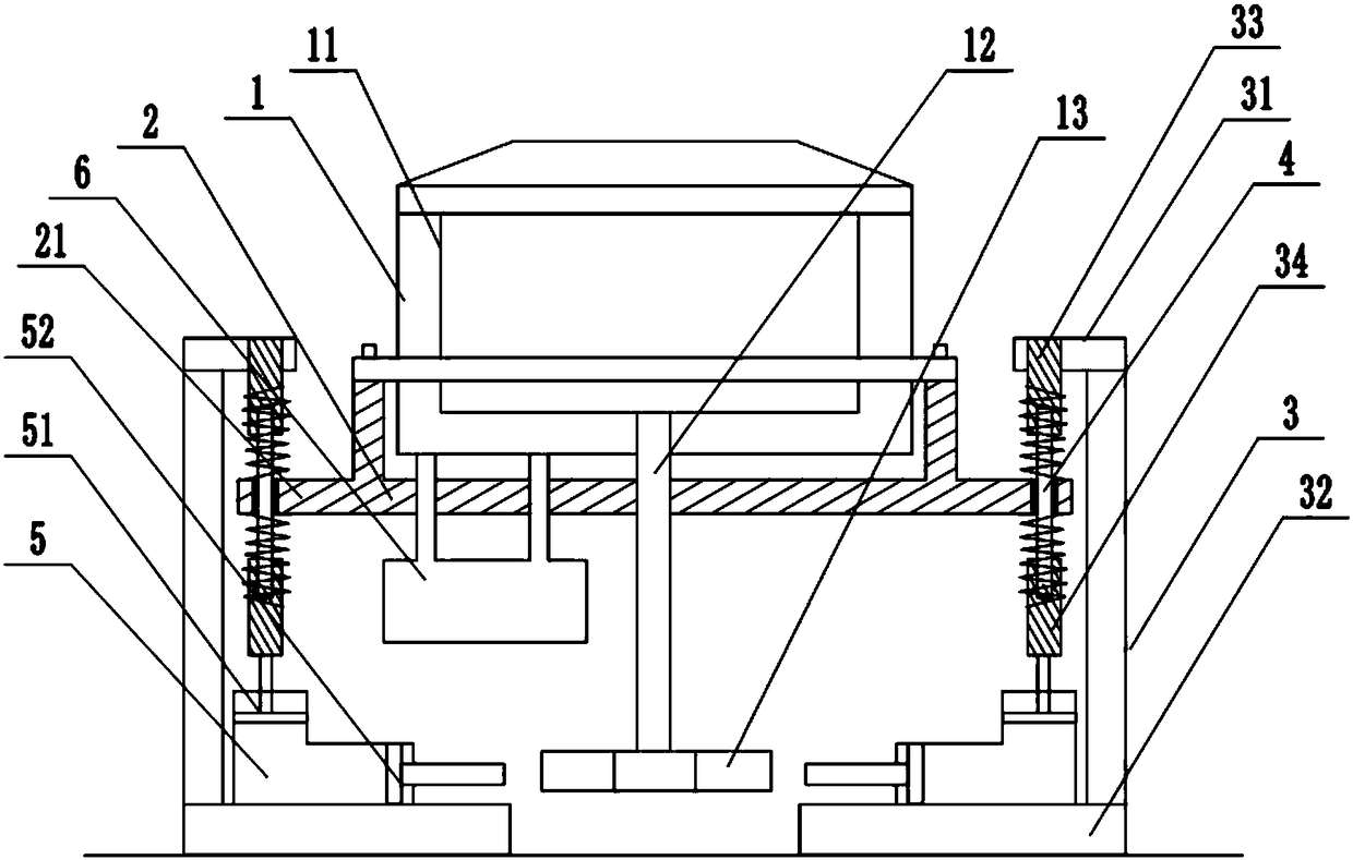
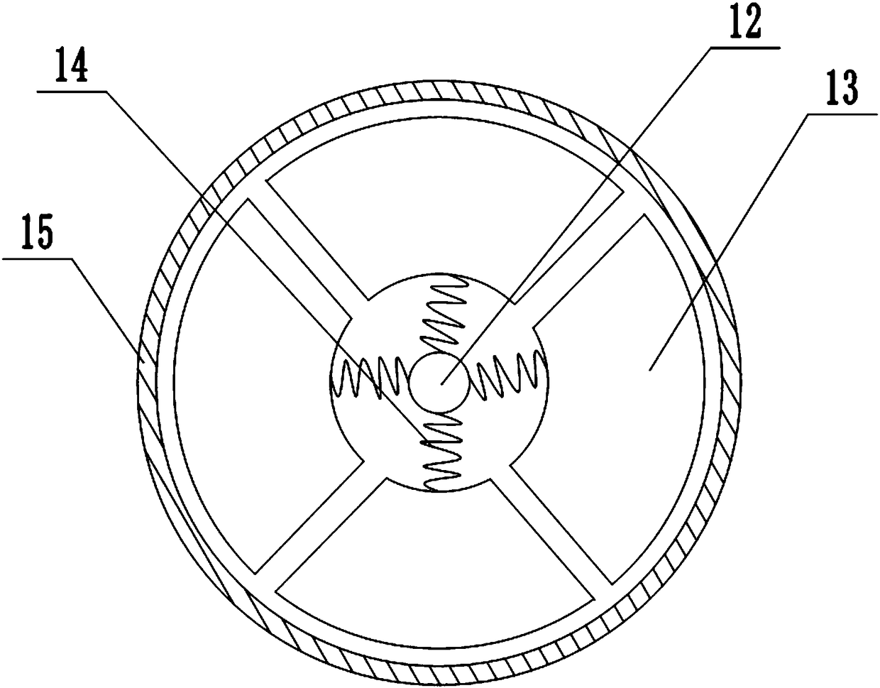
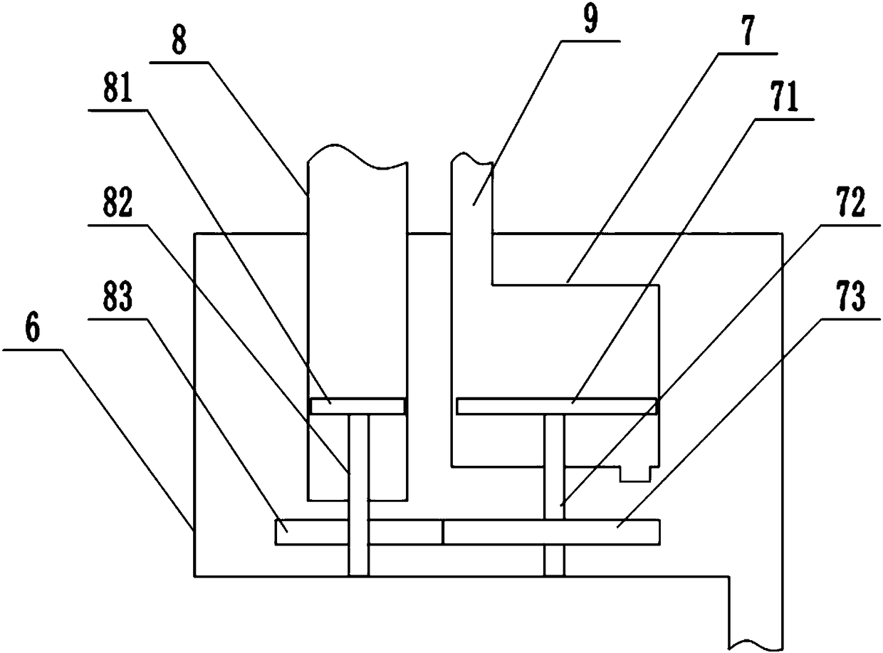
[0018] The reference signs in the drawings of the description include: dehydrator 1, inner cylinder 11, rotating rod 12, arc block 13, tension spring 14, elastic collar 15, base 2, connecting part 21, buffer frame body 3, upper support Part 31, lower support part 32, upper adjustment rod 33, lower adjustment rod 34, guide rod 4, L-shaped hydraulic cylinder 5, first piston 51, second piston 52, noise reduction device 6, vacuum box 7, fan blade 71, the second rotating shaft 72, the second gear 73, the liquid catheter 8, the helical blade 81, the first rotating shaft 82, the first gear 83, and the air guiding tube 9.

[0019] The embodiment is basically as attached Figures 1 to 3 Shown: a fabric dehydrator with an adaptive damping device, including a dehydrator 1 and a base 2 for supporting the dehydrator 1, the base 2 is provided with an outwardly extending connecting por...


PUM


Abstract

The application relates to the technical field of weaving machines and discloses a cloth dehydrator with a self-adaptive damping device. The cloth dehydrator comprises a dehydrator body and a base. Aconnection part is arranged on the base and corresponds to a buffer rack body. An upper support part, a lower support part and guide rods are arranged on the buffer rack body. The guide rods are inserted with upper springs and lower springs in a sleeving manner. The lower springs are equipped with L-shaped hydraulic cylinders. First piston rods of the L-shaped hydraulic cylinders are fixedly connected with lower adjusting rods. An inner drum is arranged in the dehydrator body and rotatably connected with the inner wall of the dehydrator body. The bottom of the inner drum is connected with a rotary rod. The side surface of the rotary rod is equipped with multiple arc blocks. The arc blocks correspond to second piston rods of the L-shaped hydraulic cylinders. According to the vibration frequency of the inner drum of the dehydrator body, the arc blocks squeeze the second piston rods to different extent and indirectly generate different degrees of compression deformation to the lower springs. Therefore, the self-adaptive adjusting buffer effect of the vibration frequency of the dehydrator body is achieved.

Description

technical field [0001] The invention relates to the technical field of textile machinery, in particular to a fabric dehydrator. Background technique [0002] The buffer structure adopted by the existing printing and dyeing cloth dehydrator is to set a vertical shaft in the buffer frame, and two buffer springs are inserted into the vertical shaft, and the protrusions on the side wall of the dehydrator main body are inserted into the on the shaft and clamped between two buffer springs. The above-mentioned buffer device has the following disadvantages: when the buffer spring has been used for a long time, the elastic fatigue life of the buffer spring is reduced, which affects the elastic force. At this time, it is necessary to replace the buffer spring to achieve adjustment. Frequent replacement of the buffer spring greatly increases maintenance costs and reduces Improve the efficiency of the dehydrator. [0003] The invention patent of Chinese patent authorization announceme...

Claims


Application Information

Patent Timeline
Patent Type & Authority Applications(China)
IPC IPC(8): F16F15/023F16F15/04F16M5/00D06B15/10
CPCD06B15/10F16F15/023F16F15/04F16M5/00
Inventor 孙九荣
Owner 宁波隆锐机械制造有限公司
Why Eureka
Try Eureka