Measuring device and method for rotor axial force of double-screw compressor

A technology for measuring devices and compressors, applied in measuring devices, force/torque/work measuring instruments, instruments, etc., can solve problems such as inability to measure, increase in compressor monitoring and maintenance costs, and inaccuracy, saving maintenance time and Maintenance cost, stable measurement and real-time monitoring, the effect of accurate installation location

Active Publication Date: 2018-09-14
XI AN JIAOTONG UNIV
View PDF13 Cites 7 Cited by
  • Summary
  • Abstract
  • Description
  • Claims
  • Application Information

AI Technical Summary

Problems solved by technology

However, due to the compact structure of the screw compressor, the installation space of the sensor in the bearing cavity is very limited, and the size of the sensor itself must be small enough; in addition, the bearing of the compressor has oil lubrication and frictional heat during operation, which also directly affects the sensor's performance. performance
[0003] In the existing force measuring ring for axial force measurement of rotating machinery, the strain gauge is pasted on the force bearing surface to sense the axial strain of the force measuring ring, but the output signal is extremely sensitive due to the extremely small deformation of the force measuring ring. Low, the scope of use is limited; in addition, because the force measuring device needs to be close to the thrust bearing, there is a lot of oil in the bearing cavity, and the space is very narrow, which makes the installation and operation of the force measuring ring extremely difficult, and it is very easy to cause damage to the force measuring ring or test Inaccurate
Moreover, once it is damaged, it needs to be replaced as a whole, resulting in increased monitoring and maintenance costs of the compressor
[0004] It is reported that the standard stress sensor is installed on both sides of the thrust bearing with a tray, but the tray is directly stressed during the process of measuring the axial force, causing the tray to be easily damaged. Once the tray is damaged, it will easily lead to deviations in the measurement results, or even fail to measure

Method used


Image

  • Measuring device and method for rotor axial force of double-screw compressor
  • Measuring device and method for rotor axial force of double-screw compressor
  • Measuring device and method for rotor axial force of double-screw compressor

Examples


Embodiment Construction

[0031] The present invention will be described in further detail below in conjunction with the accompanying drawings and embodiments.

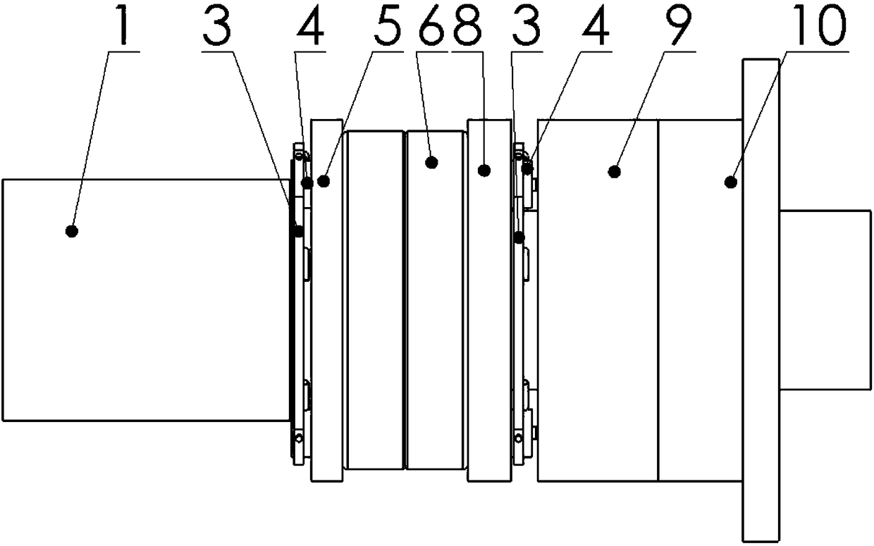
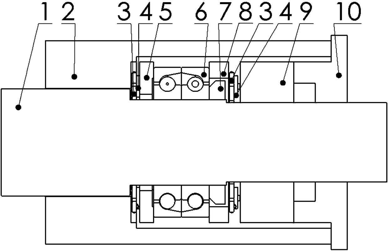
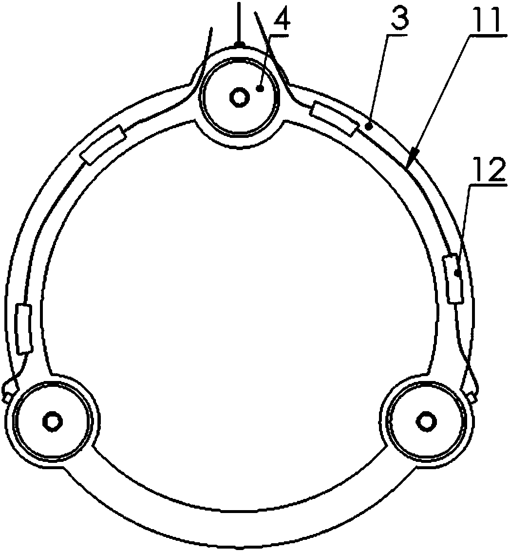
[0032] see figure 1 and figure 2 The measuring device for the axial force of the rotor of the twin-screw compressor according to the present invention includes two stress sensor assemblies arranged in the bearing cavity of the exhaust seat of the twin-screw compressor. The bearing cavity includes a housing 2 and a The shaft seal sleeve 9 at one end, the thrust bearing 6 is installed in the bearing cavity, and the rotor protruding shaft 1 is sleeved in the thrust bearing 6. The stress sensor assembly includes a bracket 3 and a standard stress sensor 4 arranged on the bracket 3, the bracket 3 is a ring structure as a whole, so as to be installed and positioned along the axial direction of the compressor rotor (i.e. figure 1The rotor shown in the figure extends out from the shaft 1 and runs through the stress sensor assembly), and the bracket ...


PUM


Abstract

The invention discloses a measuring device and method for rotor axial force of a double-screw compressor. The measuring device mainly comprises two groups of stress sensors arranged on two sides of athrust bearing at an exhaust end of the double-screw compressor, each group of stress sensor assembly comprises three standard stress sensors, stress is uniform, stable measurement and real-time monitoring can be realized, and the three standard stress sensors are fixed on a corresponding bracket and are mounted and positioned by through holes. The measuring device adopts two-way force measurementdesign, can accurately measure the direction and magnitude of axial force without interference to operation of a rotor.

Description

technical field [0001] The invention belongs to the field of axial force monitoring and measurement of rotary machines, and in particular relates to a measuring device and method for axial force of a twin-screw compressor rotor. Background technique [0002] With the rapid development of general mechanical design technology and machining capabilities, twin-screw compressors are widely used in metallurgy, power, petrochemical, electromechanical, food processing and other fields due to their stable and efficient working characteristics; and because of these characteristics, their With the increasing requirements of new energy and environmental protection, the scope of application is getting bigger and bigger, and the requirements for it are getting higher and higher. Therefore, the problems of twin-screw compressors in terms of force, vibration, and noise have also received more and more attention from engineers and technicians. Among the various forces and moments that the s...

Claims


Application Information

Patent Timeline
Patent Type & Authority Applications(China)
IPC IPC(8): G01L5/12
CPCG01L5/12
Inventor 邢子文张震张运运于志强
Owner XI AN JIAOTONG UNIV
Why Eureka
Try Eureka