
Portable concrete reinforcing steel bar detector

A technology of concrete steel bars and detectors, which is applied in the field of detectors, can solve the problems of data cable skin wear, affect the appearance, and fail to troubleshoot, and achieve the effects of improving work efficiency, increasing service life, and improving accuracy

Inactive Publication Date: 2018-09-14
郭玉龙
View PDF0 Cites 4 Cited by
  • Summary
  • Abstract
  • Description
  • Claims
  • Application Information

AI Technical Summary

Problems solved by technology

[0006] The purpose of the present invention is to provide a portable concrete steel bar detector to solve the problem that the existing portable concrete steel bar detector in the above-mentioned background technology has no access opening for maintenance personnel to open during the use of the portable concrete steel bar detector. When a fault occurs, the fault cannot be checked in time, which reduces the work efficiency of the maintenance personnel and delays the use. During the use of the existing portable concrete steel bar detector, due to the long data line, there is no fault during use and storage. The device that is convenient to organize the data lines makes the data lines scattered around, which not only affects the appearance but also wears the skin of the data lines, affects the accuracy of the portable concrete steel bar detector, and shortens the service life of the data lines.

Method used


Image

  • Portable concrete reinforcing steel bar detector
  • Portable concrete reinforcing steel bar detector
  • Portable concrete reinforcing steel bar detector

Examples


Embodiment Construction

[0021] The following will clearly and completely describe the technical solutions in the embodiments of the present invention with reference to the accompanying drawings in the embodiments of the present invention. Obviously, the described embodiments are only some, not all, embodiments of the present invention. Based on the embodiments of the present invention, all other embodiments obtained by persons of ordinary skill in the art without making creative efforts belong to the protection scope of the present invention.

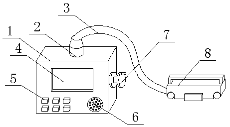
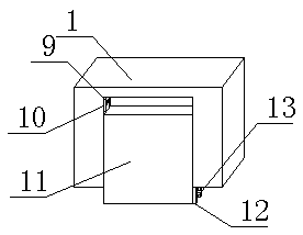
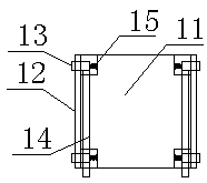
[0022] see Figure 1-Figure 4 , the present invention provides a technical solution: a portable concrete steel bar detector, including a dismantling device and a winding device, the dismantling device includes a sliding inspection door 11, a detector main body 1, and the surface of the detector main body 1 is provided with a sliding inspection door 11 Compatible grooves, both sides of the groove are provided with integrated structure chute 10, between the chut...


PUM


Abstract

The invention discloses a portable concrete reinforcing steel bar detector. The portable concrete reinforcing steel bar detector comprises a dismounting device, and a rolling device; the dismounting device comprises a slide access door, and a detector main body; the surface of the detector main body is provided with a groove matching the slide access door; the two sides of the groove are providedwith slide grooves of one-piece structures; a spacing groove is arranged between the slide grooves; the two sides of the slide access door are provided with stop blocks; the stop blocks are designed to be cooperative with the spacing groove; slide blocks are arranged on the external side of each stop block with relative to the two sides of the spacing groove. The slide access door is arranged on one side of the detector main body, so that it is convenient for in time checking and repairing of faults by maintenance personnel when detector failure is caused, the maintenance personnel working efficiency is increased effectively, and delaying of working progress is avoided; a winding wheel is arranged on one side of the detector main body, so that surface wearing caused by data line scatteringis avoided, influences on detection results are avoided, the service life of data line is prolonged effectively, and the accuracy of detection results is increased.

Description

technical field [0001] The invention belongs to the technical field of detectors, and in particular relates to a portable concrete steel bar detector. Background technique [0002] The detector is widely used, mainly used in petrochemical industry, electric power industry, aviation shipbuilding industry, paper industry, textile industry, metallurgical industry, etc., with hardware or software equipment that can find and solve various fault characteristics, these characteristics include special protocol package Decoding, special pre-programming failure testing, packet filtering and packet transmission. The concrete steel bar detector is an integrated multi-functional steel bar testing equipment for testing the corrosion degree of steel bars. [0003] Yet existing portable concrete reinforcement detector still has some deficiencies in the process of using, and existing portable concrete reinforcement detector is in use: [0004] 1. During the use of the existing portable con...

Claims


Application Information

Patent Timeline
Patent Type & Authority Applications(China)
IPC IPC(8): G01N17/00
CPCG01N17/006
Inventor 郭玉龙
Owner 郭玉龙
Learn More