
A milling cutter positioning and clamping device for machine vision inspection

A technology of machine vision inspection and clamping equipment, which is applied in the direction of instruments, measuring devices, scientific instruments, etc., and can solve the problems of increasing the difficulty of image processing, low degree of automation, and inaccurate positioning of objects to be measured

Active Publication Date: 2021-04-27
XIJING UNIV
View PDF7 Cites 0 Cited by
  • Summary
  • Abstract
  • Description
  • Claims
  • Application Information

AI Technical Summary

Problems solved by technology

The shortcomings of today's milling cutter positioning and clamping equipment are as follows: (1) Most of the milling cutter positioning and clamping equipment currently used for machine vision inspection is still in the laboratory research stage, and there are very few that can be used for actual testing
(2) Because machine vision detection has high requirements on the light source environment, the image acquisition process of the milling cutter needs to use a backlight, and the only milling cutter positioning and clamping equipment currently uses a manipulator to hold the milling cutter for shooting. In this way, there will be a manipulator in the collected images, which increases the difficulty of post-image processing, and seriously affects the detection results
(3) The degree of automation is not high, and flow testing cannot be performed. Most of them need to manually place the test piece on the clamping device, which will make the positioning of the test object inaccurate and affect the detection accuracy.
(4) The milling cutter positioning and clamping equipment used for machine vision inspection on the market can only complete the end face of the milling cutter (axial, secondary cutting edge) and the arc surface of the milling cutter (radial, main cutting edge) A clamping positioning, cannot complete the clamping positioning of the main and auxiliary cutting edges at the same time

Method used


Image

  • A milling cutter positioning and clamping device for machine vision inspection
  • A milling cutter positioning and clamping device for machine vision inspection
  • A milling cutter positioning and clamping device for machine vision inspection

Examples


Embodiment Construction

[0025] The technical solutions of the present invention will be clearly and completely described below in conjunction with the embodiments and drawings. Apparently, the described embodiments are only some of the embodiments of the present invention, not all of them. Based on the embodiments of the present invention, all other embodiments obtained by persons of ordinary skill in the art without making creative efforts belong to the protection scope of the present invention.

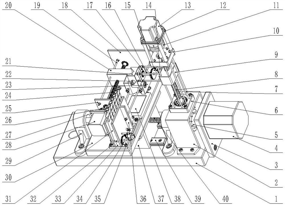
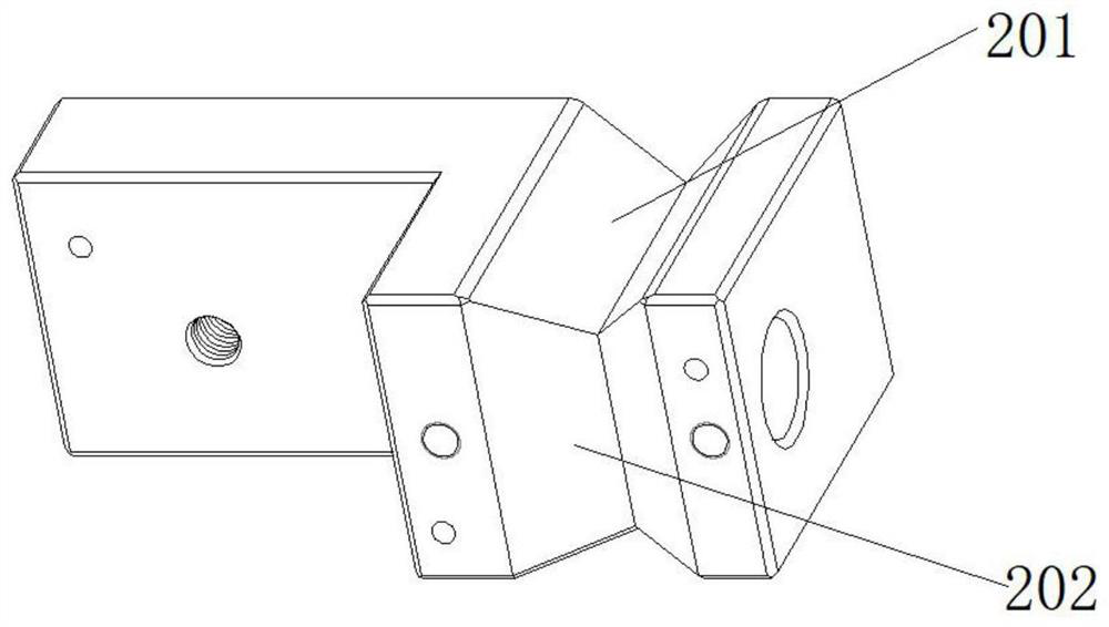
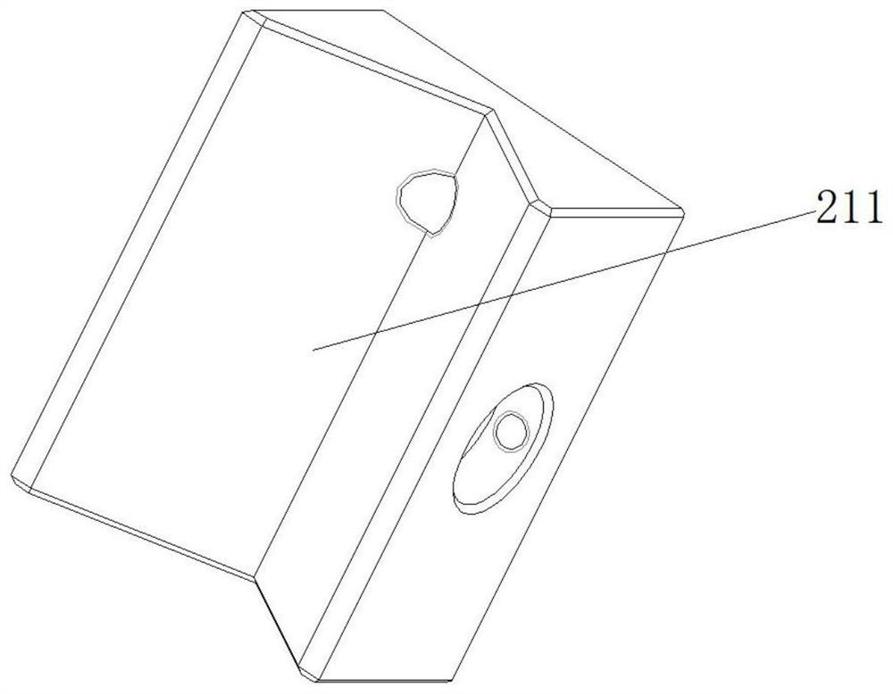
[0026] Such as figure 1 As shown, a milling cutter positioning and clamping device for machine vision inspection includes a base 1, a first motor support plate 3 is installed on one side of the base 1, an X-axis stepping motor 4 is fixed on it, and the X-axis stepping motor 4 Connect the input end of the X-axis screw 40 through the first coupling 5, the two ends of the X-axis screw 40 are supported on the base 1 through the bearing and the bearing seat 29, the X-axis screw 40 and the first slider 37 Coope...


PUM


Abstract

A milling cutter positioning and clamping device for machine vision inspection, including a base, on which is provided a first slider driven by an X-axis stepping motor through an X-axis screw, a pedestal is installed above the first slider, and a pedestal is installed above the pedestal. There is a milling cutter clamp driven by a Y-axis stepping motor through a Y-axis screw, and an LED backlight is installed above the pedestal; beside the milling cutter clamp, there is a rotating clamp connected to the rotating spindle, which is driven by the R-axis Driven by a stepping motor, the R-axis stepping motor is fixed on the second slider; the second slider is driven by a Z-axis stepping motor through a Z-axis screw, and a milling cutter conveying device is arranged above the pedestal, and the equipment includes four degrees of freedom , the present invention can realize the image acquisition of the main and auxiliary cutting edges of the tested milling cutter, can realize no-fixture shooting, and can also realize the flow detection of the milling cutter, has a high degree of automation, and improves the detection accuracy and efficiency.

Description

technical field [0001] The invention relates to the technical field of machine vision precision measurement, in particular to a milling cutter positioning and clamping device for machine vision detection. Background technique [0002] Milling cutter is a tool used in milling, mainly used for processing planes, steps, grooves, forming surfaces and cutting off workpieces. Since the working environment of the milling cutter is extremely complex, wear and damage are always unavoidable, so regular inspection work is a necessary condition to ensure the normal operation of the milling cutter. With the rise of machine vision inspection technology, milling cutter positioning and clamping equipment is often used in the grinding and breakage of milling cutters to provide a better inspection environment and improve inspection efficiency and inspection accuracy. The shortcomings of today's milling cutter positioning and clamping equipment are as follows: (1) Most of the milling cutter p...

Claims


Application Information

Patent Timeline
Patent Type & Authority Patents(China)
IPC IPC(8): G01N21/88
CPCG01N21/8851G01N2021/8887
Inventor 张博吴松林张敏
Owner XIJING UNIV
Learn More